Light source unit and projector

a light source unit and projector technology, applied in the direction of picture reproducers using projection devices, lighting and heating apparatus, instruments, etc., can solve the problems of difficult profiling, difficulty in normal polarization conversion, and failure of polarization conversion, so as to reduce the amount of light the effect of excellent heat resistance and efficient output from the light source uni

Inactive Publication Date: 2005-09-29
SEIKO EPSON CORP
View PDF12 Cites 33 Cited by
  • Summary
  • Abstract
  • Description
  • Claims
  • Application Information

AI Technical Summary

Benefits of technology

[0021] The phase plate may be formed of a member of an inorganic compound such as crystal, and mica plate. The phase plate formed of the above described inorganic compound member has relatively excellent heat resistance. Therefore, the phase plate formed of the above described inorganic compound member can be laminated on the light emitting unit.
[0022] When the light emitting unit, the phase plate, and the reflecting-type polarizing plate are laminated, the light from the light emitting unit passes through the reflecting-type polarizing plate without going through the air. I...

Problems solved by technology

If the phase plate is damaged, it becomes difficult to perform normal polarization conversion.
Therefore, polarization conversion may fail even if the reflecting-type polarizing plate and the phase plate are provided adjacent to the light emitting unit.
However, a disadvantage of this technology is that profiling is difficult since the sapphire substrate is very hard, and it is not easy to perform chemical processing such as oxidation.
Therefore, another technology is still required to easily decrease the light taken into the light emitting unit without performing processing of the sap...

Method used


Image

  • Light source unit and projector
  • Light source unit and projector
  • Light source unit and projector

Examples


first embodiment

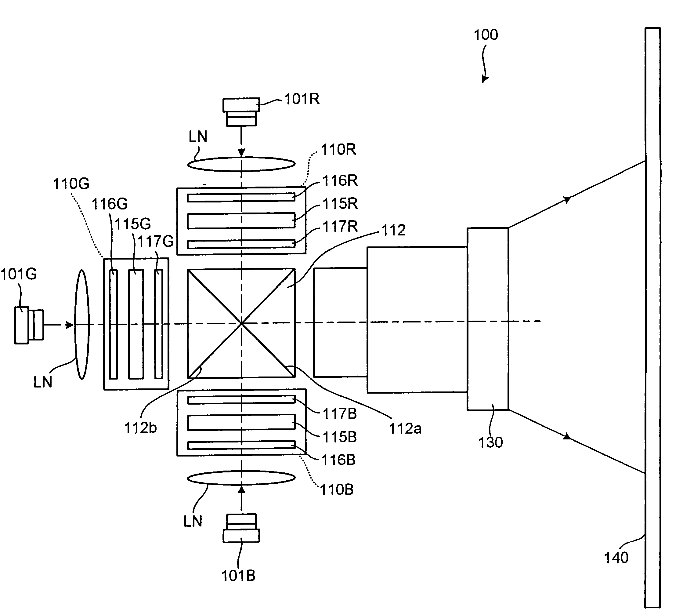
[0051]FIG. 1 is a schematic block diagram of a projector 100 according to the present invention. The projector 100 includes an R-light source unit 101R that supplies R light, which is a first color light, a G-light source unit 101G that supplies G light, which is a second color light, and a B-light source unit 101B that supplies B light, which a third color light.

[0052] The R-light source unit 101R supplies polarized light in a specific vibration direction, for example, p-polarized R-light. The R light comes from the R-light source unit 101R, passes through a lens LN, and enters into an R-light spatial light modulator 110R. The R-light spatial light modulator 110R is a transmission-type liquid-crystal-display unit that modulates R light according to the image signal. The R-light spatial light modulator 110R includes a liquid crystal panel 115R, a first polarizing plate 116R, and a second polarizing plate 117R.

[0053] The first polarizing plate 116R transmits the p-polarized R-light ...

second embodiment

[0088] The gap is not provided between the light emitting unit 201 and the λ / 4 phase plate 404, and the reflector 502 has the height that is substantially same as the thickness of the light emitting unit 201. The reflector 502 may be extended up to a position closer to the emission side than the position where the light emitting unit 201 is provided, as in the light source unit in the In the light source unit in this embodiment, since the reflector 502 has a tapered surface, diffusion of light that travels toward the side of the light emitting unit 201 is prevented, and the light is guided to the λ / 4 phase plate 404.

[0089] A micro prism array 507, which is an optical element, is provided on a surface of the reflecting-type polarizing plate 205, and the surface is located on a side where the λ / 4 phase plate 404 side is not arranged. The micro prism array 507 outputs the light that passes through the reflecting-type polarizing plate 205. The micro prism array 507 is formed of m...

fourth embodiment

[0103] The micro prism array 1107 is provided in such a manner that fine micro prisms 1108 are arranged in an array in a rectangular area on the glass substrate 1105. The micro prism array 1107 has the same configuration as that of the micro prism array 507 in the fourth embodiment shown in FIG. 6. The micro prisms 1108 are formed, for example, to have a height 10 times as long as the wavelength of the R light.

[0104] The light is generated in the semiconductor layer 1111 in the light emitting unit 1101 and emitted from the light emitting unit 1101 via the sapphire substrate 1112. For example, light is generated in the light emitting unit 1101 in the optical axis direction Z and is emitted directly from the light emitting unit 1101. Light L4 that is generated in the semiconductor layer 1111 and enters into the emission-side interface of the sapphire substrate 1112 at an angle equal to or larger than the critical angle will be explained.

[0105] When the light L4 enters into the emissi...


PUM


Abstract

It is an object of the present invention to provide a light source unit that can supply bright light efficiently. The light source unit includes a light emitting unit that emits light, a phase plate that polarizes the light from the light emitting unit to produce a first polarized light and a second polarized light that is polarized in a different direction with respect to the first polarized light, a reflecting-type polarizing plate that transmits the first polarized light and reflects the second polarized light; and a reflector that is provided near both the light emitting unit and the phase plate, and reflects back a third light, which is a portion of the first polarized light and that passes through the phase plate, to the phase plate.

Description

CROSS-REFERENCE TO RELATED APPLICATIONS [0001] The present document incorporates by reference the entire contents of Japanese priority document, 2004-87164 filed in Japan on Mar. 24, 2004 and Japanese priority document, 2004-87615 filed in Japan on Mar. 24, 2004. BACKGROUND OF THE INVENTION [0002] 1) Field of the Invention [0003] The present invention relates to a light source unit and a projector, and more specifically, relates to a light source unit that uses a light emitting diode (hereinafter, “LED”). [0004] 2) Description of the Related Art [0005] Conventionally, several technologies have been proposed for a light source unit used for a liquid-crystal-type spatial-light-modulator in a projector. Japanese Patent Application Laid-Open Nos. 2003-98483 and 2000-221499 disclose technologies that the reflecting-type polarizing plate and the phase plate are used together for polarization conversion. [0006] Japanese Patent Application Laid-Open No. 2003-98483 discloses a lighting syste...

Claims


Application Information

Patent Timeline
IPC IPC(8): G02F1/13357H04N9/31
CPCF21Y2101/02G02F1/13362G02F2001/133507G02F2001/133607H01L33/486H01L2924/0002H01L33/58H01L33/64H01L2924/00F21Y2115/10G02F1/133507G02F1/133607G02B27/18G02B27/28
Inventor TAKEDA, TAKASHI
Owner SEIKO EPSON CORP
Why Eureka
Try Eureka