Radio telecommunications network, and a method of selecting base station antennas for connection with a mobile user terminal

a mobile user terminal and radio telecommunications technology, applied in the direction of site diversity, transmission monitoring, synchronisation arrangement, etc., can solve the problems of time delay involved in the mobile user terminal, time delay involved in the transfer of a cell from the monitored/detected set into the active set, and delay is often long, so as to reduce the delay

Active Publication Date: 2005-09-29
ALCATEL-LUCENT USA INC +1
View PDF5 Cites 27 Cited by
  • Summary
  • Abstract
  • Description
  • Claims
  • Application Information

AI Technical Summary

Benefits of technology

[0009] The inventor(s) found a way to reduce this delay by providing that cells can be in a set in which a control channel has been established but not a corresponding data channel.
[0010] An example of the present invention is a method of selecting base station antennas for connection with a mobile user terminal in a radio telecommunications network, comprising the following steps. Test transmissions between the mobile user terminal and base station antennas are made, and the received test transmissions processed to determine respective signal path quality for each of the base sta

Problems solved by technology

There is a time delay involved in the mobile user terminal setting up a radio connection with a cell.
In other words there is a time delay involved in transferring a cell from the monitored/detected set into the active set.
The delay is mainly due to the time required to establish radio synchronisation of the control channels between the mobile user terminal and the network via the new cell.
The delay is often long, which is problematic because during the delay the mobile user terminal does not benefit from the desired radio connection with that cell.
Also, the longer the delay is, the more likely it is that the sign

Method used


Image

  • Radio telecommunications network, and a method of selecting base station antennas for connection with a mobile user terminal
  • Radio telecommunications network, and a method of selecting base station antennas for connection with a mobile user terminal
  • Radio telecommunications network, and a method of selecting base station antennas for connection with a mobile user terminal

Examples


Embodiment Construction

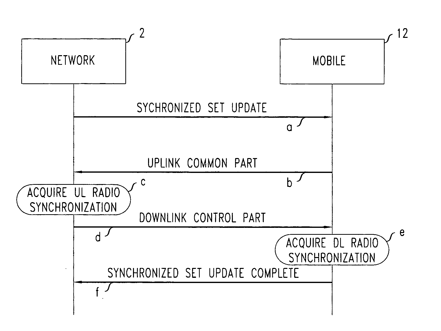
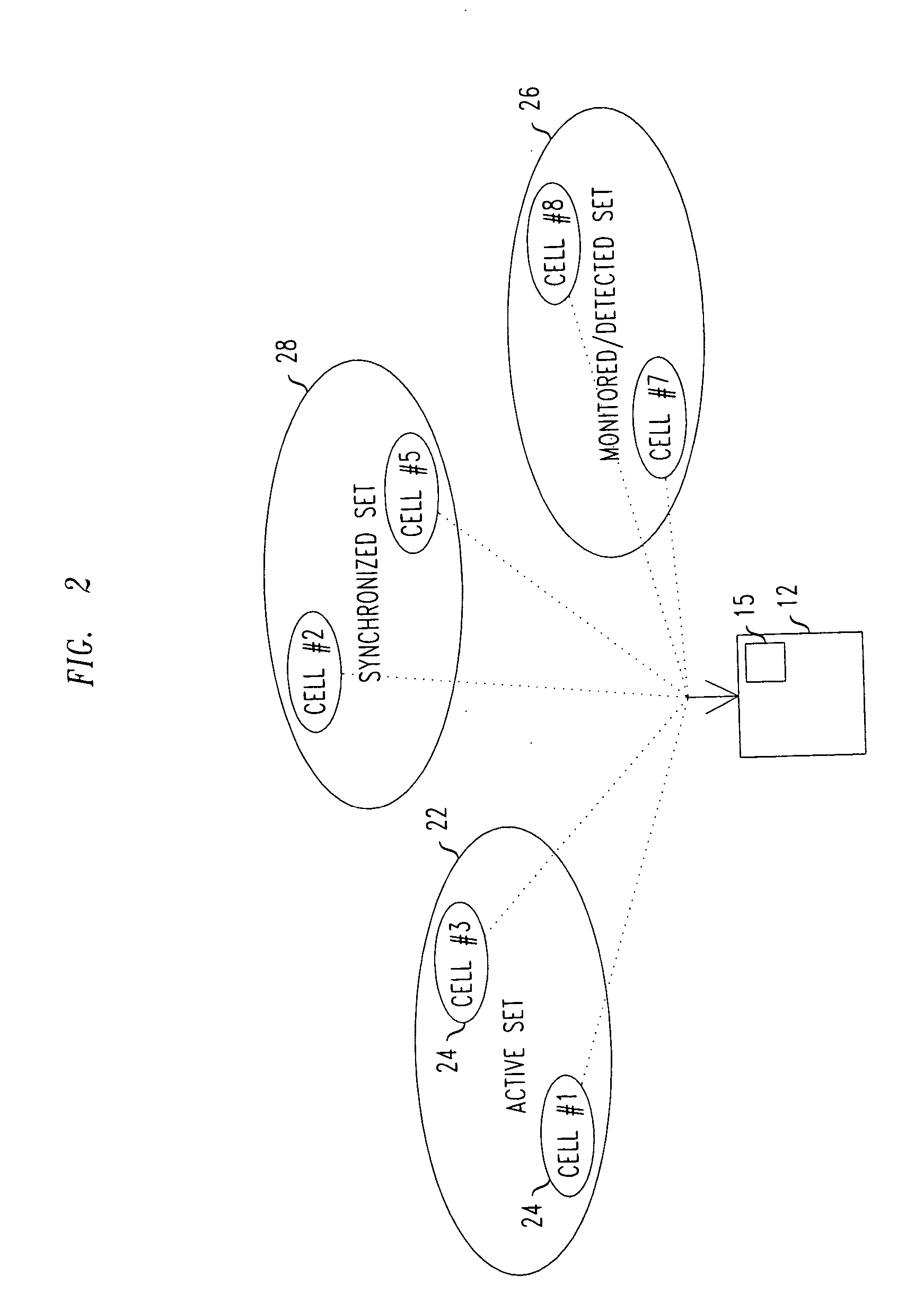
[0016] From considering a known system, the inventors realised that an intermediate set of cells can be maintained between the monitored / detected set and active set. This new set, known as the synchronised set, contains cells having radio connections in the form of control channels established, but not data channels. As cells in this set are already time synchronised between base station and mobile user terminal, the delay, between the time a cell is selected as suitable for handover to transferring that cell into the active set, is greatly reduced.

The Network

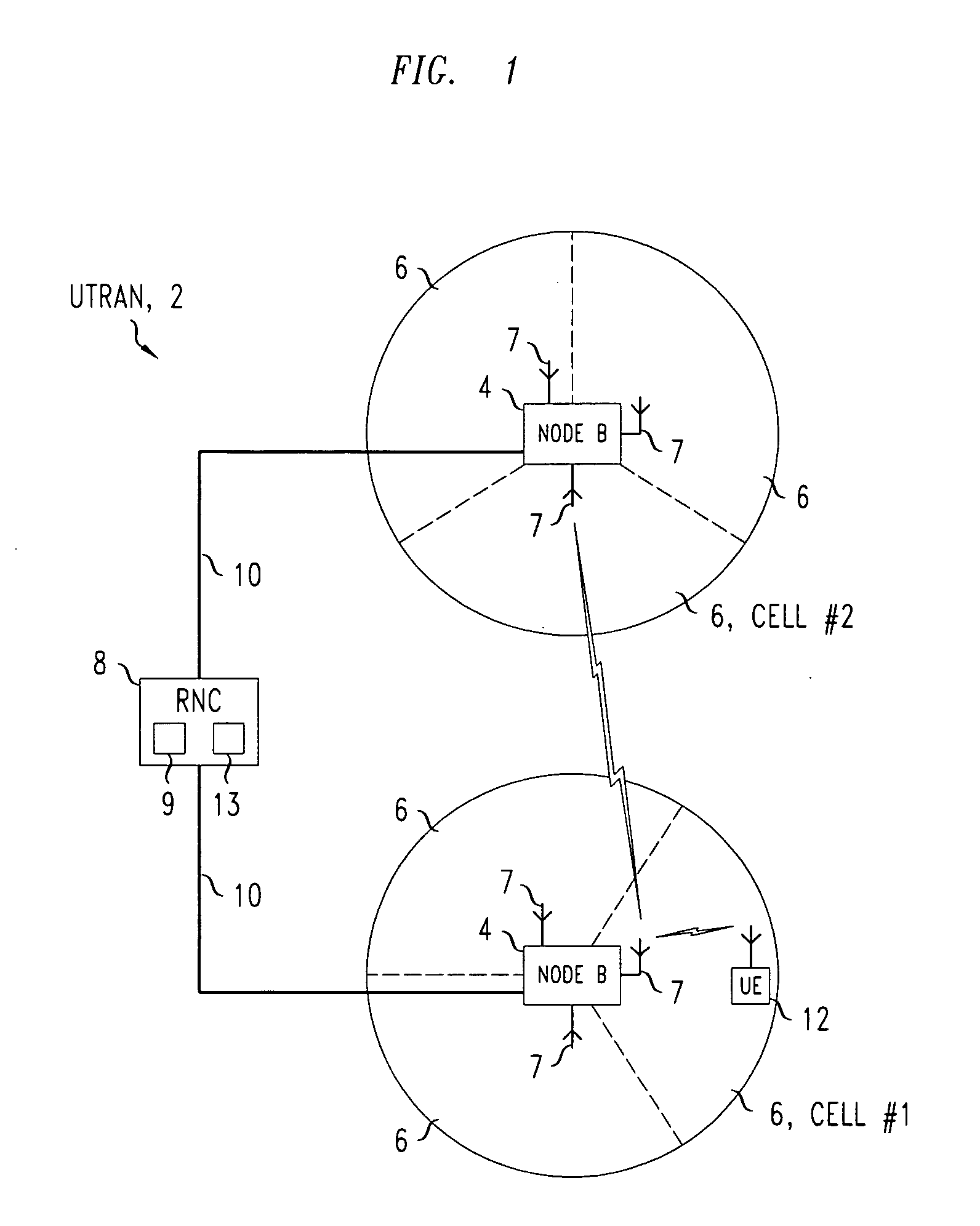
[0017] The network is a Universal Mobile Telecommunications System (UMTS) terrestrial access network (UTRAN), which is a type of wideband code division multiple access (CDMA) network for mobile telecommunications. The UTRAN network is basically as shown in FIG. 1. Only one radio network controller and two base stations of the UTRAN network 2 are shown for simplicity. As shown in this Figure, the UTRAN network 2 includes base...


PUM


Abstract

In the method provided, test transmissions between the mobile user terminal and base station antennas are made, and the received test transmissions processed to determine respective signal path quality for each of the base station antennas. Upon the determined signal path quality exceeding a first predetermined threshold, but being less than a second predetermined threshold higher than the first predetermined threshold, the mobile user terminal is connected to the corresponding base station antenna by control channels but not data channels so as to be time synchronised. Upon the determined signal path quality exceeding the second predetermined threshold, the mobile user terminal is connected to the corresponding base station antenna by both control channels and data channels so as to be call connected.

Description

FIELD OF THE INVENTION [0001] The present invention relates to a radio telecommunications network, and a method of selecting base station antennas for connection with a mobile user terminal in a radio telecommunications network. DESCRIPTION OF THE RELATED ART [0002] In wireless telecommunications networks of code division multiple access (CDMA) type, soft handover is commonplace. Soft handover is also known as soft handoff. Soft handover is where a mobile user terminal has radio connections with the network via a number of different cells at the same time, for example to multiple antennas of a base station or to multiple base stations. The aim of soft handover is to maintain a call despite radio fading. One type of CDMA network is a Universal Mobile Telecommunications System (UMTS) network. [0003] The cells currently connected to by radio connections with the mobile user terminal are known as the active set. The mobile user terminal communicates using these cells. The mobile user te...

Claims


Application Information

Patent Timeline
IPC IPC(8): H04B7/26H04B7/02H04W36/18H04W56/00
CPCH04B7/022H04W56/00H04W36/18H04W28/24H04W36/30
Inventor CAO, QIANGCHARRIERE, PATRICK GEORGES VENCESLASLIM, SEAU SIANSAPIANO, PHILIP CHARLES
Owner ALCATEL-LUCENT USA INC
Why Eureka
Try Eureka