
Golf club head

a golf club and head technology, applied in the field of golf club head, can solve the problems of difficult to effectively apply correcting motion to the head, difficult to expect that the ball is accurately hit by, spot by a lot of average golfers, etc., and achieve the effect of improving the directionality of the hit ball

Active Publication Date: 2005-09-29
SUMITOMO RUBBER IND LTD
View PDF16 Cites 72 Cited by
  • Summary
  • Abstract
  • Description
  • Claims
  • Application Information

AI Technical Summary

Benefits of technology

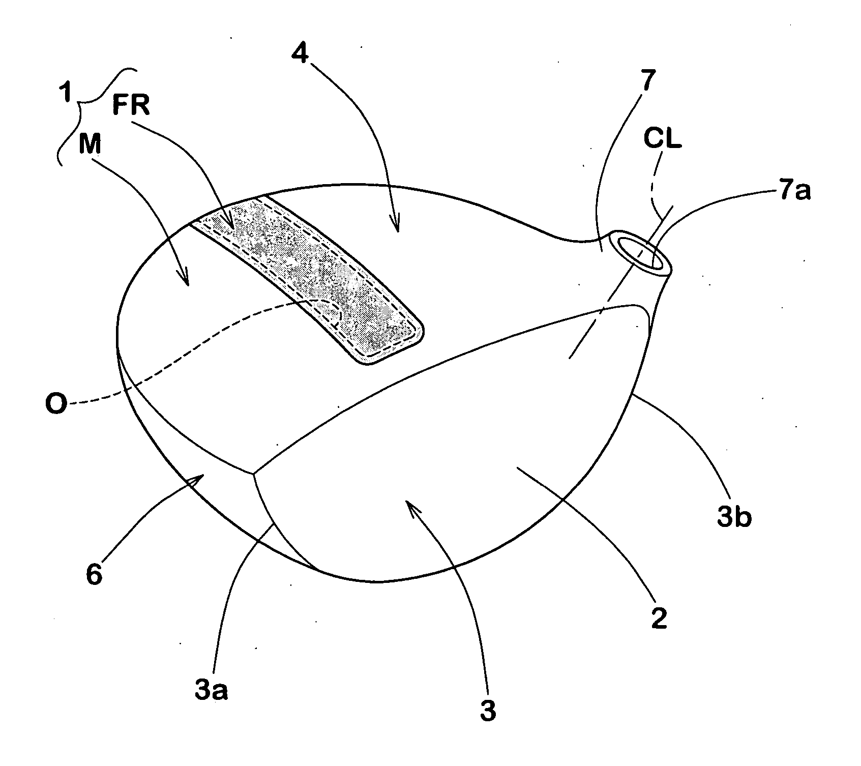
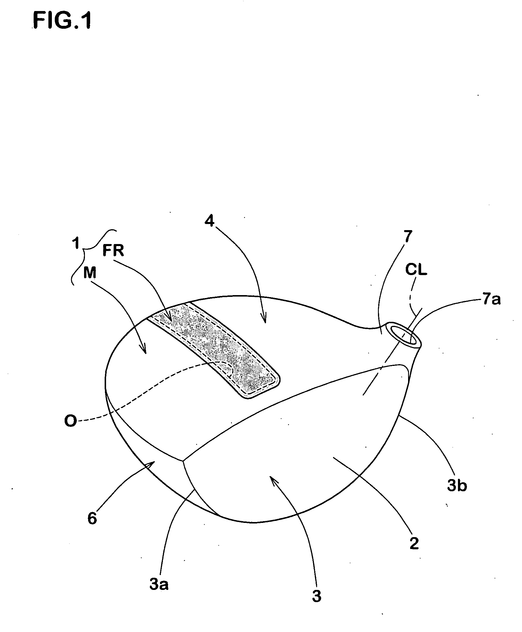
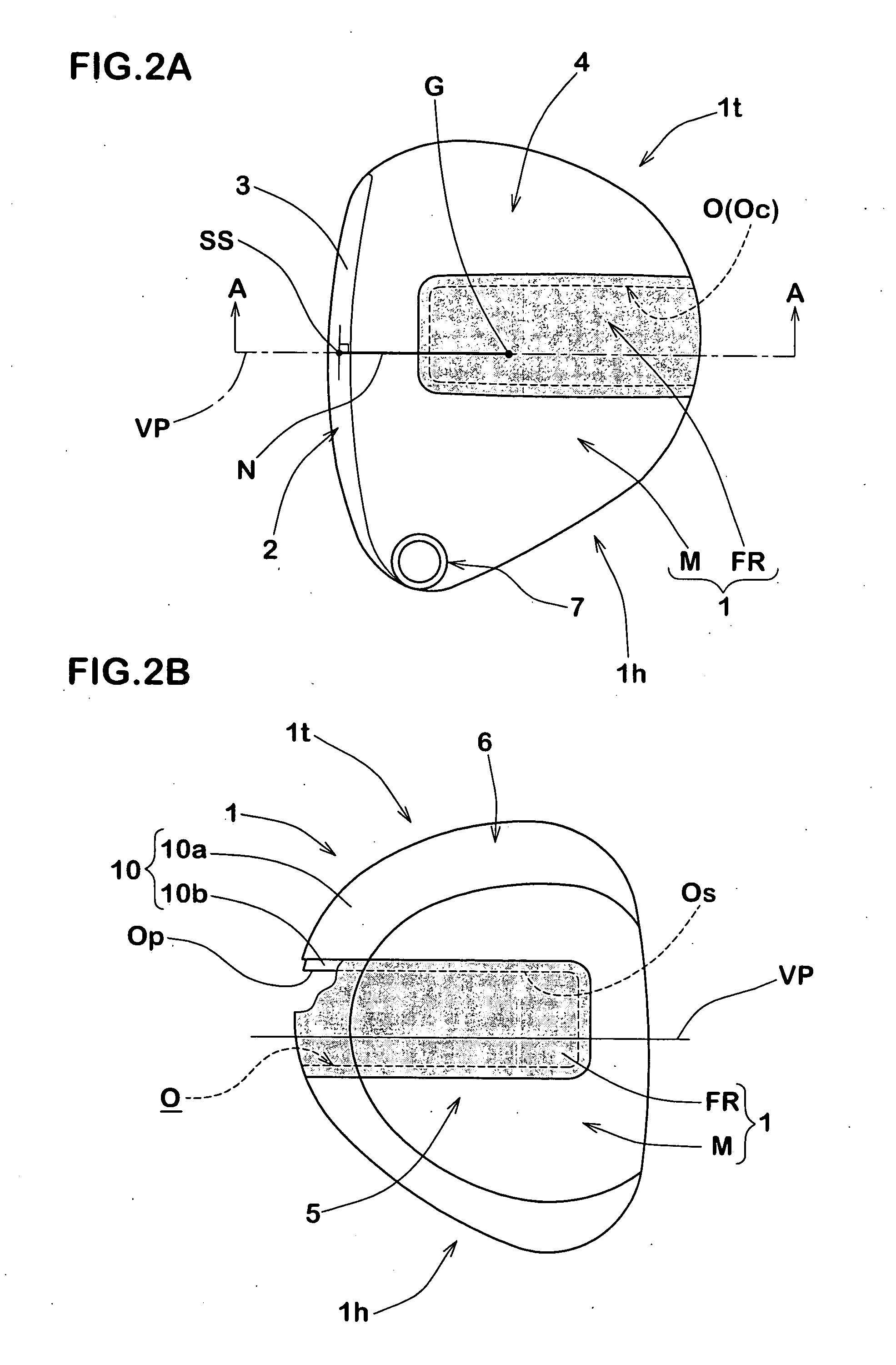
[0006] The present invention is made by taking the actual condition mentioned above into consideration, and an object of the present invention is to provide a golf club head serving for improving a directionality of a hit ball, on the basis of a golf club head structured such as to include a head base body made of a metal material having at least one opening portion, and a cover body arranged in the opening portion and made of a low specific gravity material, and structured such that a surface area St of the cover body covering the opening portion included in a head toe side portion is made larger than a surface area Sh of the cover body covering the opening portion included in a head heel side portion, and a weight of the head heel side portion is limited with respect to the entire weight of the head.
[0009] The golf club head mentioned above can improve a turn-back of the face surface in the down swing motion from the top to the impact. Accordingly, since it is possible to hit the ball in the address state or a direction of the face surface similar thereto, the directionality of the hit ball is improved.

Problems solved by technology

However, actually, it is hard to expect that the ball is accurately hit by the sweet spot by a lot of average golfers except a professional golfer and some seniors, and the golfers having the skill mentioned above generally hit the ball at a position displaced to a toe side or a heel side from the sweet spot of the face surface.
Accordingly, the correcting motion is hard to be effectively applied to the head having the great moment of inertia due to the great moment of inertia.

Method used


Image

  • Golf club head
  • Golf club head
  • Golf club head

Examples


examples

[0061] In order to confirm the effect of the present invention, a wood type driver head having the head volume of 420 cm3 is manufactured on the basis of the specification shown in Table 1. The head base body is integrally cast by using a titanium alloy (Ti-6Al-4V, specific gravity of about 4.4) for doing away with the dispersion, and thereafter precisely formed in the opening portion by applying a numerical control process. In all the examples, a receiving portion having a width of 5 mm and receiving the cover body is provided in the entire periphery around the opening portion. Further, the cover body is formed in accordance with an internal pressure molding method by using a prepreg obtained by impregnating a carbon fiber having an elastic modulus in tension of 275 GPa with an epoxy resin. Further, with respect to each of the heads, the following measurements and tests are carried out.

[0062] In the standard state, the moment of inertia around the vertical axis passing through the...


PUM


Abstract

An object of the invention is to improve a directionality of a hit ball. The invention provides a golf club head (1) having a face portion (3), a crown portion (4), a sole portion (5) and a side portion (6). The golf club head includes a head base body (M) made of a metal material and provided with at least one opening portion (O), and a cover body (FR) arranged in the opening portion (O) and made of a lower specific gravity material having a specific gravity smaller than the metal material. In a head toe side portion (1t) and a head heel side portion (1h) virtually sectioned by a vertical surface (VP) including a normal line (N) drawn from a head gravity point (G) to a face surface (2) in a standard state, a surface area (St) of the cover body (FR) covering the opening portion (O) included in the head toe side portion (1t) is made larger than a surface area (Sh) of the cover body (FR) covering the opening portion included in the head heel side portion (1h), and a weight (Wh) of the head heel side portion (1h) is set to 55 to 75% of the entire weight (W) of the head.

Description

BACKGROUND OF THE INVENTION [0001] The present invention relates to a golf club head which can improve a directionality of a hit ball. [0002] A golf club head is designed such that an accurate distance and directionality can be obtained by hitting a ball by a sweet spot of a face surface. However, actually, it is hard to expect that the ball is accurately hit by the sweet spot by a lot of average golfers except a professional golfer and some seniors, and the golfers having the skill mentioned above generally hit the ball at a position displaced to a toe side or a heel side from the sweet spot of the face surface. In this case, the head generates a micro rotational motion around a gravity point, and a side spin in an inverse direction to the rotational direction of the head is generated in the ball which is in contact with the face surface due to a frictional force. Accordingly, the hit ball is curved to an unintended direction. The operation mentioned above has been known as a gear ...

Claims


Application Information

Patent Timeline
IPC IPC(8): A63B53/04A63B102/32
CPCA63B53/0466A63B2053/0437A63B2053/0433A63B2209/02A63B53/0433A63B53/0437
Inventor KUMAMOTO, TOMIO
Owner SUMITOMO RUBBER IND LTD
Learn More