Orthopedic intramedullary fixation system

Inactive Publication Date: 2005-09-29
WOLL BIOORTHOPEDICS
View PDF49 Cites 92 Cited by
  • Summary
  • Abstract
  • Description
  • Claims
  • Application Information

AI Technical Summary

Benefits of technology

[0027] The present invention overcomes the deficiencies of the prior art by providing a clavicle repair apparatus with reduced risk of injury to the subclavian artery. An intramedullary apparatus is provided that is suitable for use in curved bone segments without presenting a high risk of damaging surrounding tissue. The various embodiments of the present invention also provide an intramedullary support device for use on curved bone segments that does not include a rigid internal rod portion, and which is s

Problems solved by technology

Slings are used alone in certain circumstances where use of invasive apparatus or implants presents an unacceptable risk of injury to a patient.
For example, slings are often used without any invasive apparatus to repair a fractured clavicle because implantation of known invasive bone repair apparatus to repair a fractured clavicle can risk life threatening damage to the patient's subclavian artery or damage to other vessels, nerves, nerve bundles, vital organs or surrounding tissues.
Since invasive repair of a fractured clavicle presents medical risk, patients having a fractured clavicle often forgo the benefits offered by various invasive apparatus and implants.
Further, use of slings alone often allows misaligned bone segments to heal such that a visibly conspicuous deformation or a weak area remains which is susceptible to re-injury.
Accordingly, such devices are typically unsuitable for implantation in curved bone segments.
Such devices also present a high risk of drilling through a bone segment into surrounding tissue, and are therefore not well suited for

Method used


Image

  • Orthopedic intramedullary fixation system
  • Orthopedic intramedullary fixation system
  • Orthopedic intramedullary fixation system

Examples


Embodiment Construction

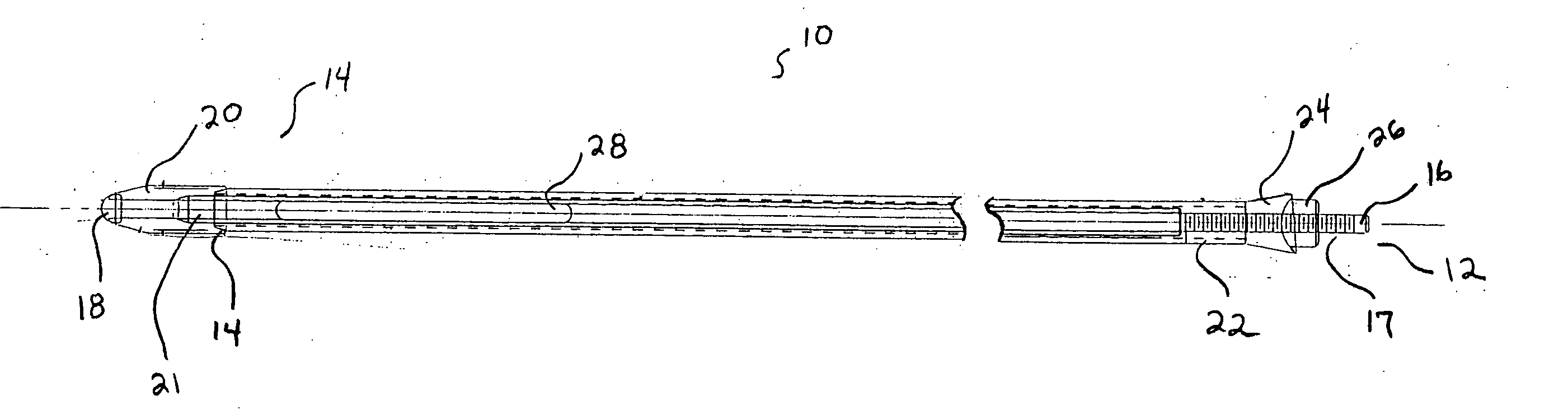
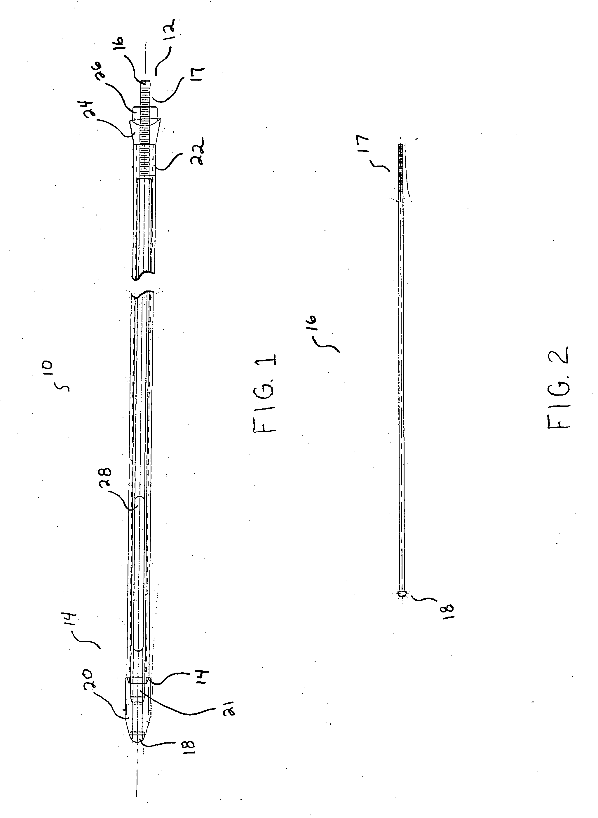
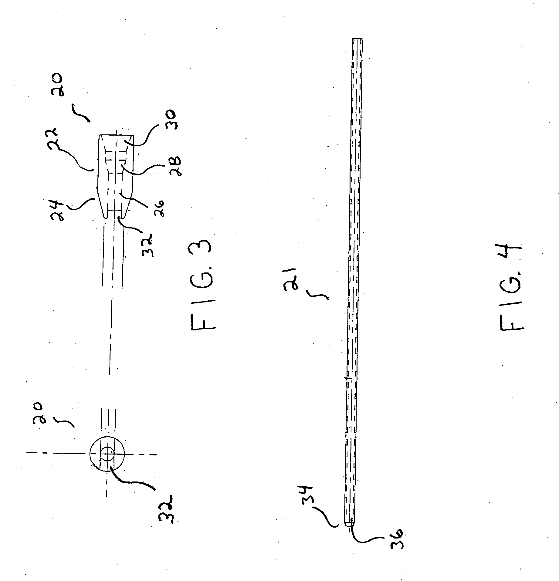
[0045] In FIG. 1, the components of a long bone compression apparatus 10 having a proximal end 12 and a distal end 14 according to the an illustrative embodiment of the invention are shown assembled together in a cross sectional view. A guide wire 16 extends from the distal end 14 to the proximal end 12 of the compression apparatus and includes a threaded portion 17 on the proximal end of the guide wire 16 and a distal end stop 18 disposed on the distal end of the guide wire 16. A dilator 20 is disposed over the guide wire 16 adjacent to the distal end stop 18. As disclosed herein, the term ‘distal’ refers to the element or portion furthest from the threaded portion 17 of the guide wire 16 and the term ‘proximal’ refers to the element or portion closest to the threaded portion 17 of the guide wire 16.

[0046] In the embodiment shown in FIG. 1, an inner tube 21 is disposed over the guide wire 16 and an outer tube 22 is disposed over the inner tube 21. Both the inner tube 21 and outer ...


PUM


Abstract

A system and method for repairing fractured long bones. A guide wire is inserted through an opening drilled in a proximal bone segment and pushed through the intramedullary cavity of the proximal bone segment, across the fracture site and into the intramedullary cavity of a distal bone segment. A dilator is inserted over the guide wire and pushed through the intramedullary cavity into the distal bone segment to a stop at the distal end of the guide wire. A flexible tube having a radially expandable distal portion is then pushed over the guide wire into the distal bone segment and against the dilator. A compression nut is threaded over the proximal end of the guide wire to engage the proximal bone segment and compress the flexible tube. Compression of the flexible tube deploys the radially expandable distal portion to anchor the device in the distal bone segment.

Description

FIELD OF THE INVENTION [0001] This invention relates generally to an orthopedic support system and apparatus and more particularly to an intramedullary (IM) support apparatus and method of use thereof for supporting fractured long bones. The IM support apparatus according to the present invention is minimally invasive and provides improved alignment of bone segments. BACKGROUND OF THE INVENTION [0002] Various methods and apparatus have long been used for positioning, stabilizing and supporting bone segments to repair bone fractures in humans and animals. Simple external apparatus such as slings and splints are well known and are still used alone or in combination with invasive apparatus to repair broken bones. Slings are used alone in certain circumstances where use of invasive apparatus or implants presents an unacceptable risk of injury to a patient. For example, slings are often used without any invasive apparatus to repair a fractured clavicle because implantation of known invas...

Claims


Application Information

Patent Timeline
IPC IPC(8): A61B17/17A61B17/72A61B19/00
CPCA61B17/1717A61B17/7225A61B17/7258A61B2017/1782A61B17/7291A61B2019/304A61B17/7275A61B2090/034A61B17/1782
Inventor WOLL, CHRISTIANDICKENS, DUANEWOODS, RICHARD
Owner WOLL BIOORTHOPEDICS
Why Eureka
Try Eureka