Method for detecting electric-mechanical-brake pad drag and/or calculating actuator efficiency

a technology of actuator efficiency and emb pad drag, which is applied in the field of electric mechanical brake, can solve problems such as undesirable conditions in the description of the emb pad drag

Inactive Publication Date: 2005-09-29
BWI CO LTD SA +1
View PDF43 Cites 11 Cited by
  • Summary
  • Abstract
  • Description
  • Claims
  • Application Information

AI Technical Summary

Benefits of technology

[0009] Several benefits and advantages are derived from one or more of the methods of the invention. In one example of the first and / or second method of the invention, being able to detect EMB pad drag allows, in one embodiment, the EMB electronic control unit to adjust the EMB pad re-home position to eliminate such EMB pad drag which will improve gas mileage and improve vehicle handling. In one example of the third and / or fourth method of the invention, being able to calculate a no-load EMB actuator efficiency allows a calculation of a low efficiency to indicate (depending on temperature) that the EMB actuator, or a component thereof, is in need of repair or replacement. SUMMARY OF THE DRAWINGS

Problems solved by technology

Brake pad drag describes an undesirable condition, whether the vehicle is in motion or not, when the brake pad is supposed to be released but actually remains in contact with the brake rotor.

Method used


Image

  • Method for detecting electric-mechanical-brake pad drag and/or calculating actuator efficiency
  • Method for detecting electric-mechanical-brake pad drag and/or calculating actuator efficiency
  • Method for detecting electric-mechanical-brake pad drag and/or calculating actuator efficiency

Examples


Embodiment Construction

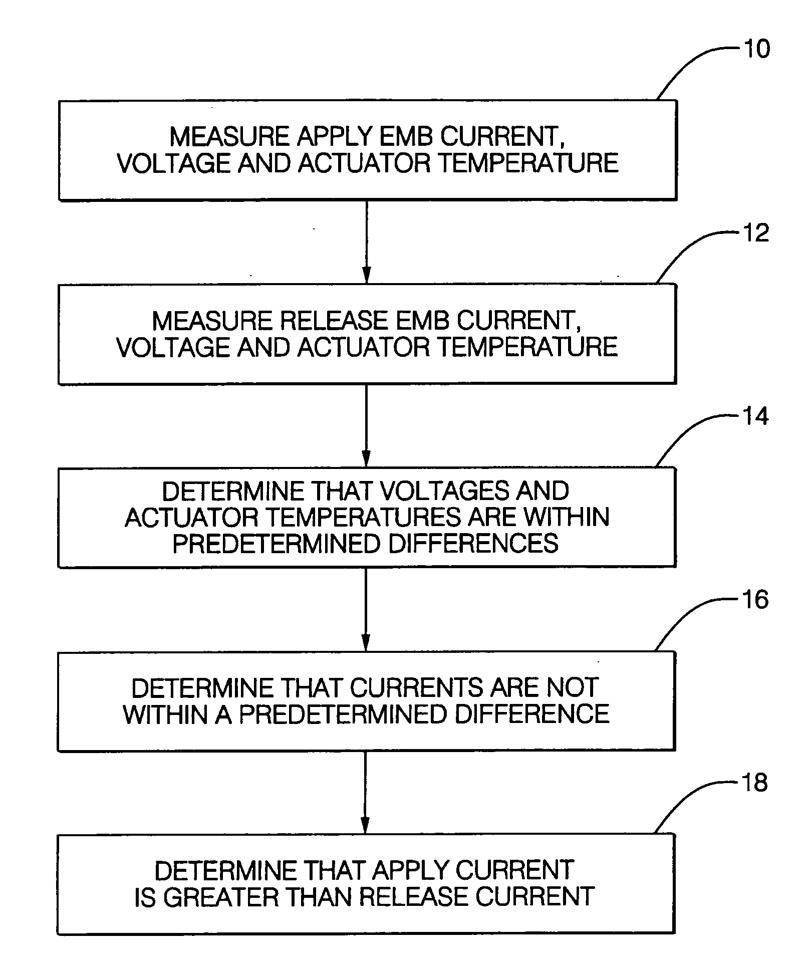
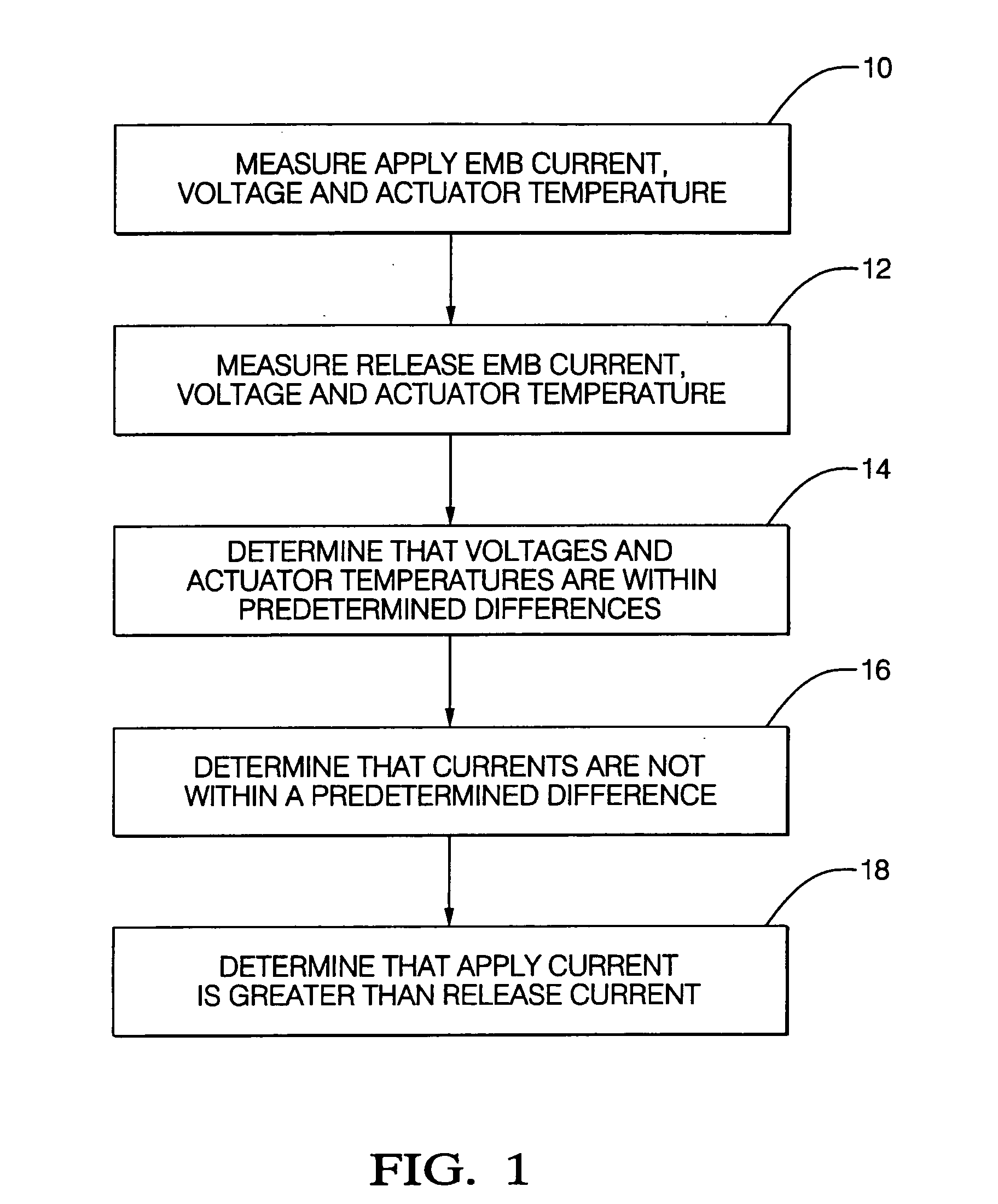
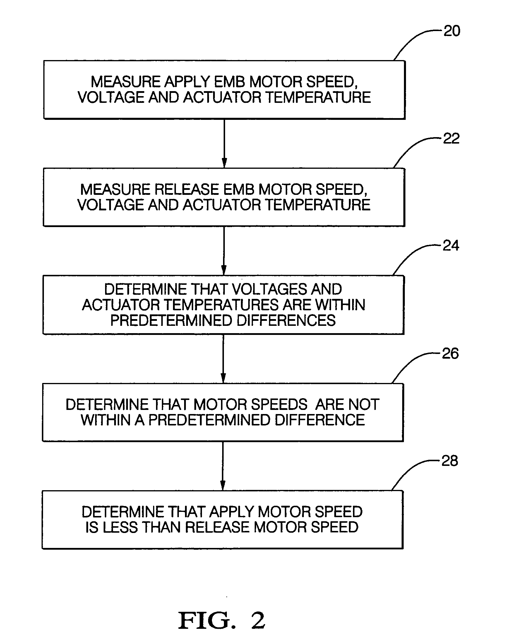
[0014] Referring now to the drawings, FIG. 1 shows a first method of the invention which is for detecting electric-mechanical-brake (EMB) pad drag and which includes steps a) through e). Step a) is labeled as “Measure Apply EMB Current, Voltage And Actuator Temperature” in block 10 of FIG. 1. Step a) includes measuring an apply EMB current, an apply EMB voltage, and an apply EMB actuator temperature during an open-loop apply of the EMB pad. Step b) is labeled as “Measure Release EMB Current, Voltage And Actuator Temperature” in block 12 of FIG. 1. Step b) includes measuring a release EMB current, a release EMB voltage, and a release EMB actuator temperature during an open-loop release of the EMB pad. Step c) is labeled as “Determine That Voltages And Actuator Temperatures Are Within Predetermined Differences” in block 14 of FIG. 1. Step c) includes determining that the apply and release EMB voltage magnitudes are within a predetermined voltage difference and that the apply and relea...


PUM


Abstract

Electric-mechanical-brake (EMB) pad drag is determined from measurements (which can include estimations) of EMB voltage, EMB actuator temperature, and either EMB current or EMB motor speed during an open-loop apply of the EMB pad and during an open-loop release of the EMB pad. An open-loop EMB actuator efficiency is calculated when certain conditions of the same measurements apply, whereupon the EMB actuator efficiency is calculated using at least the apply or release EMB current and a corresponding apply or release preselected (such as a nominal) EMB current or is calculated using at least the apply or release EMB motor speed and a corresponding apply or release preselected (such as a nominal) EMB motor speed.

Description

CROSS REFERENCE TO RELATED APPLICATIONS [0001] The present application claims priority of U.S. Provisional Application No. 60 / 555,722 filed Mar. 23, 2004.TECHNICAL FIELD [0002] The present invention relates generally to an electric mechanical brake (EMB), and more particularly to a method for detecting EMB pad drag and / or calculating actuator efficiency. BACKGROUND OF THE INVENTION [0003] Conventional electric mechanical brakes, also known as electric brake calipers, utilize an electric motor to drive a rotatable ballscrew of a ballscrew subassembly. The rotating ballscrew linearly moves a ballnut of the ballscrew subassembly. The ballnut is connected by gearing to, and linearly moves, an inner brake pad against a brake rotor of a vehicle. An outer brake pad, mounted to the caliper housing, is positioned on an opposite side of the brake rotor. During braking, the inner brake pad will be forced against the rotor and a resulting reactionary force will pull the outer brake pad into eng...

Claims


Application Information

Patent Timeline
Patent Type & Authority Applications(United States)
IPC IPC(8): F16D66/00G05B9/02G05B23/02G06F19/00
CPCF16D66/00F16D2066/006F16D2066/001
Inventor ZUMBERGE, JON T.SIMPSON, MELINDA D.LITTLEJOHN, DERON C.
Owner BWI CO LTD SA
Why Eureka
Try Eureka