Radial force variation prediction method, tangential force variation prediction method, radial run out prediction method, tire angle acceleration fluctuation prediction method, radial run out measurement apparatus, radial run out estimation method, information acquisition method, an

a technology of tangential force variation and prediction method, applied in vehicle tyre testing, electrical/magnetic diameter measurement, instruments, etc., can solve problems such as recent increas

Inactive Publication Date: 2005-09-29
BRIDGESTONE CORP
View PDF7 Cites 8 Cited by
  • Summary
  • Abstract
  • Description
  • Claims
  • Application Information

AI Technical Summary

Benefits of technology

[0010] The present invention has been achieved to solve the above-described problems, and an object thereof is to provide a radial force variation pr

Problems solved by technology

The number of cases in which higher-order components of high speed uniformity of a ti

Method used


Image

  • Radial force variation prediction method, tangential force variation prediction method, radial run out prediction method, tire angle acceleration fluctuation prediction method, radial run out measurement apparatus, radial run out estimation method, information acquisition method, an
  • Radial force variation prediction method, tangential force variation prediction method, radial run out prediction method, tire angle acceleration fluctuation prediction method, radial run out measurement apparatus, radial run out estimation method, information acquisition method, an
  • Radial force variation prediction method, tangential force variation prediction method, radial run out prediction method, tire angle acceleration fluctuation prediction method, radial run out measurement apparatus, radial run out estimation method, information acquisition method, an

Examples


first modified example (

CORRESPONDING TO THE FIRST ASPECT OF THE TENTH INVENTION)

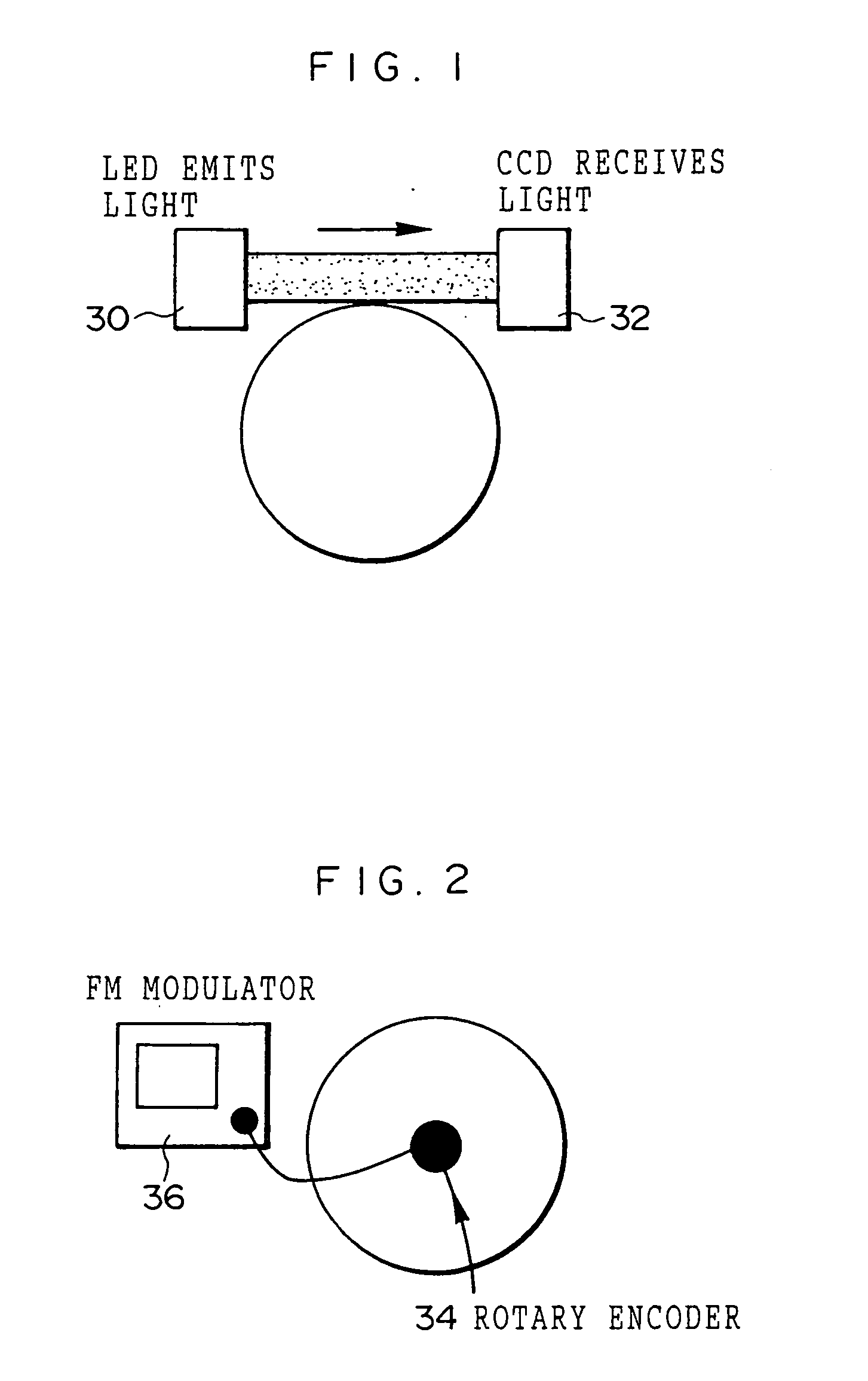
[0213] As shown in FIG. 27, an RRO measurement apparatus according to this modified example includes a light irradiation section 30 formed by light emitting diodes (LED) which serve as light emitting means to irradiate light and located so that emitted light is made to contact an outer periphery of a tire disposed in a rotatable manner, and a light receiving section 32 formed by a charge coupled device (CCD) which serves as light receiving means for receiving light irradiated from the light irradiation section 30. This structure of the apparatus is the same as that of the RRO measurement apparatus (see FIG. 1). The RRO measurement apparatus according to this modified example also includes a reference edge 31 disposed fixedly between the light irradiation section 30 and the light receiving section 32 and formed by a flat plate or the like, which serves as interrupting means for cutting off a part of light irradiated from the li...

second modified example (

CORRESPONDING TO THE SECOND ASPECT OF THE TENTH INVENTION)

[0216] As shown in FIG. 28, an RRO measurement apparatus according to this modified example is substantially the same as the RRO measurement apparatus according to the first modified example except that the displacement sensor 46 (see FIG. 18) and the reference edge 31 are connected by a connecting member 62 so as to correct swinging of the reference edge 31 with respect to a tire axis. The displacement sensor 46 is, as described above, mounted at the tire bearing fixing portion 40 via the stay 42 for mounting a sensor. As a result, the reference edge 31 is connected to the tire bearing fixing portion 40 via the displacement sensor 46 and the stay 42. Accordingly, swinging of the reference edge 31 with respect to the tire axis can be corrected.

[0217] As a result, compared with the first modified example, the RRO can be measured with a higher degree of accuracy.

third modified example (

CORRESPONDING TO THE THIRD ASPECT OF THE TENTH INVENTION)

[0218] As shown in FIG. 29, in this modified example, plural pairs of light irradiation sections 30 and the light receiving sections 32 are disposed around the tire. FIG. 29 shows, as an example, two pairs, but the present invention is not limited to the same.

[0219] In the above-described first and second embodiments and first and second modified examples, in order to predict the RRO, it is necessary that a tire should make at least one rotation. On the other hand, in the third modified example, the plural pairs of light irradiation sections 30 and light receiving sections 32 are disposed around the tire, and therefore, the RRO can be measured only by rotating the tire by an amount less than one rotation. More specifically, for example, if N pairs of light irradiation section 30 and light receiving section 32 (N is an integer of 2 or more) are disposed at regular intervals, the RRO can be measured only by rotating the tire by...


PUM


Abstract

It is possible to significantly reduce a prediction error of the high-speed RFV and the high-speed TFV in a tire having a large PRO growth amount at high speed. Three or more sample tires are extracted from each lot. The PRO and RFV are measured and the least-square method is used to predict (100) the upper and lower and front and back natural angle frequency, attenuation ratio, upper and lower spring constant, and rolling radius coefficient. By using the PRO measurement apparatus, the PRO during idling is measured. By using an AAV measurement apparatus, an actual measurement value AAVL of the angle acceleration fluctuation at a low speed is measured (102). The PRO and AAV at a high speed are predicted (104) and the actual measurement value and prediction value are used to predict the high-speed RFV and TFV.

Description

TECHNICAL FIELD [0001] The present invention relates to a radial force variation prediction method, a tangential force variation prediction method, a radial run out prediction method, and an angular acceleration fluctuation measurement method, and particularly to a radial run out prediction method, a radial force variation prediction method, a tangential force variation prediction method, and an angular acceleration fluctuation prediction method, in which radial force variation or tangential force variation can be accurately predicted by taking a radial run out (RRO) growth at high speed into consideration. RELATED ART [0002] The number of cases in which higher-order components of high speed uniformity of a tire generate noise due to vibration to thereby cause a problem has recently increased. For this reason, Japanese Patent Application Laid-Open (JP-A) No. 11-352024 discloses a method for predicting a higher-order component of high speed uniformity of a tire, in which based on low...

Claims


Application Information

Patent Timeline
IPC IPC(8): B60C19/00G01M17/02
CPCB60T2210/12G01M17/022G01M17/02
Inventor OBUNAI, KATSUO
Owner BRIDGESTONE CORP
Why Eureka
Try Eureka