Device and method of detecting rotation angle

a technology of rotating angle and detection device, which is applied in the direction of instruments, mechanical measuring arrangements, cloth making applications, etc., can solve the problems of inability to accurately transmit the rotation of the steering wheel to the vehicle control system of the car, receive a signal without evaluation, and cannot detect abnormalities quickly

Active Publication Date: 2005-10-06
PANASONIC CORP
View PDF8 Cites 15 Cited by
  • Summary
  • Abstract
  • Description
  • Claims
  • Application Information

AI Technical Summary

Benefits of technology

[0008] The present invention addresses the aforementioned problem. It is therefore an object to provide a simply structured rotation-angle detecting device capable of quickly detecting abnormalities in a rotator, a detector, and an amplifier. The rotation-angle detecting device of the present invention, which detects a rotation angle of a rotation detecting axle, has an abnormality evaluation mechanism. The mechanism further contains i) a first rotator and a second rotator, both of which have the same number of teeth and engage with the gear fixed on the rotation detecting axle; ii) a first angle-detector and a second angle-detector that detect the rotation angle of the first rotator and the second rotator, respectively; and iii) a controller for calculating the output fed from the first and second detectors and storing the calculation result. The controller i) converts the output from the first and the second detectors into a first periodic waveform and a second periodic waveform, respectively, both of which have the same crest value and then ii) stores a phase difference between the first and second periodic waveforms at a time of initial setting as an initial phase difference. The controller determines that an abnormal condition occurs when an evaluation value calculated with reference to the initial phase difference exceeds a threshold value for abnormality evaluation.

Problems solved by technology

The aforementioned detecting device, however, receives a signal without evaluating, even if the sensors have an abnormal output.
Therefore, a perceptible error can occur in measurement.
Such an error in measurement has often invited a problem that the rotation of the steering wheel cannot be accurately transmitted to the vehicle control system of a car.

Method used


Image

  • Device and method of detecting rotation angle
  • Device and method of detecting rotation angle
  • Device and method of detecting rotation angle

Examples


first exemplary embodiment

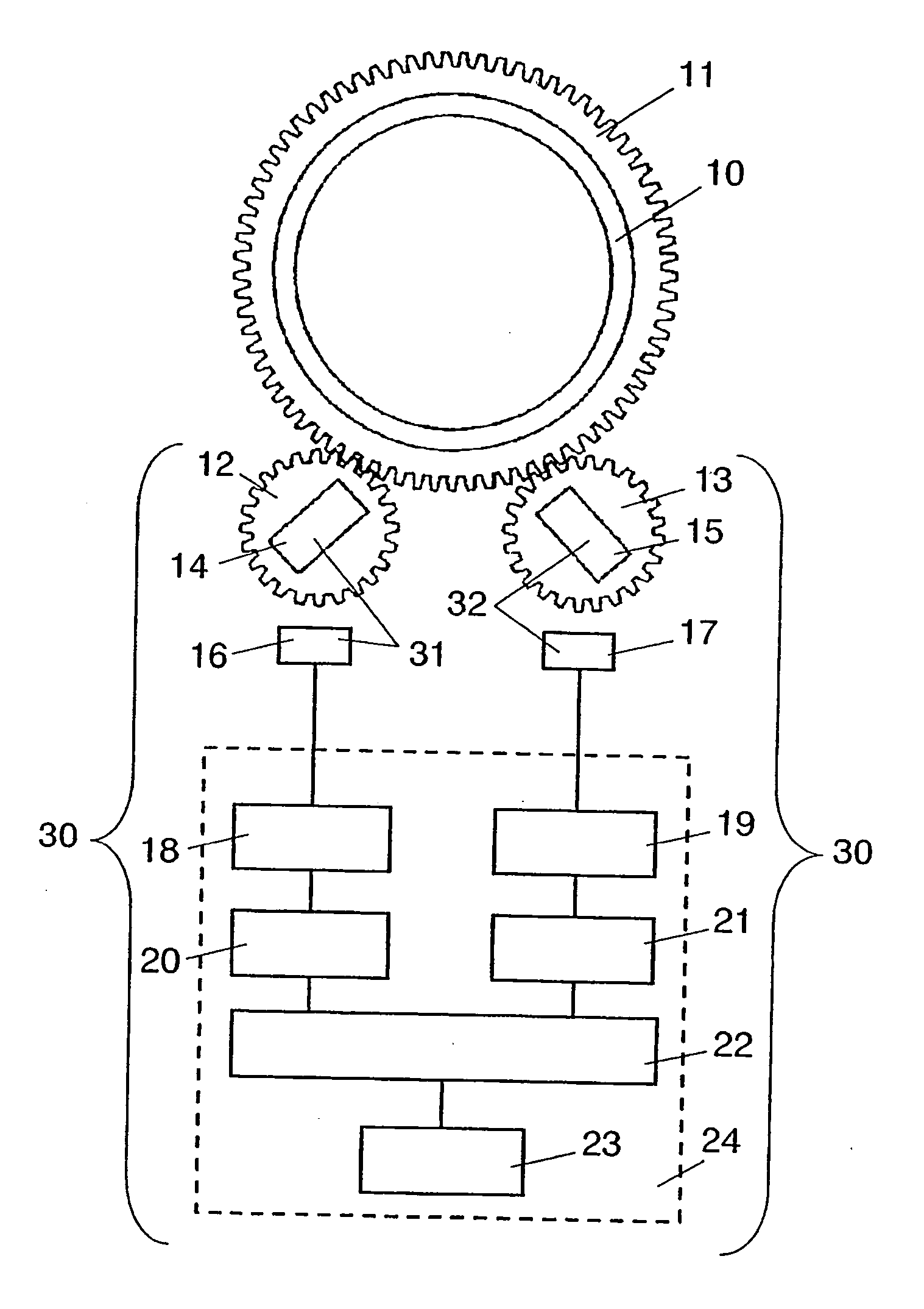
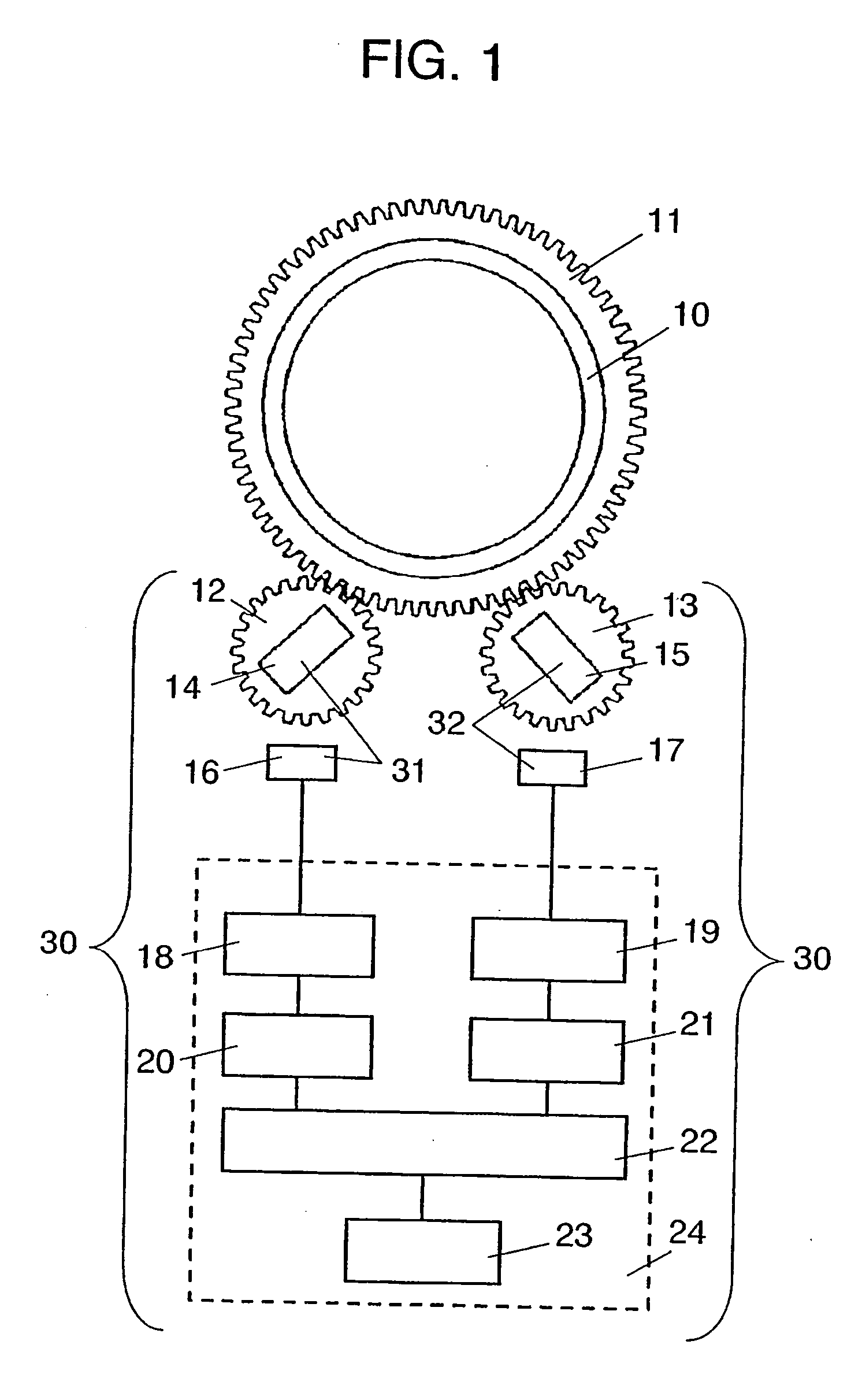
[0021]FIG. 1 shows the entire structure of the detecting device of the present invention. In FIG. 1, gear 11 of “n” number of teeth is attached with rotation detecting axle 10 of the steering wheel of a car (hereinafter referred to as rotation detecting axle 10). Further, a first rotator 12 and a second rotator 13, each of which has a gear around the periphery, are arranged so as to engage with the gear 11 of rotation detecting axle 10. The first gear 12 and the second gear 13 have the same number of teeth, “m”. Rotators 12 and 13 also have permanent magnets 14 and 15, respectively. Furthermore, magnetometric sensors 16 and 17 are disposed so as to face magnets 14 and 15, respectively. The permanent magnet 14 and the magnetometric sensor 16 constitute the first rotation-angle detecting device 31. The permanent magnet 15 and the magnetometric sensor 17 constitute the second rotation-angle detecting device 32. Signals fed from sensors 16 and 17 are amplified by amplifiers 18 and 19, a...


PUM


Abstract

The rotation-angle detecting device of the present invention contains two rotators having the same number of teeth, which engage with a gear fixed to a rotation-detecting axle as a detected object. The detecting device further includes a controller. Receiving a rotation-angle signal from the rotators, the controller amplifies the signal, performs calculations, and stores the results. The controller converts each rotation-angle signal from each rotator into each periodic waveform output having the same crest value, and stores an initial phase difference value at initial setting. In driving operations, monitoring an evaluation value calculated with reference to the initial phase difference value, the controller determines that abnormalities occurred, if the evaluation value exceeds a predetermined abnormality-evaluation threshold.

Description

TECHNICAL FIELD [0001] The present invention relates to a rotation-angle detecting device employed, for example, for a vehicle control system in an automobile and a rotation-angle detecting method using the device. BACKGROUND ART [0002] A rotation-angle detecting device has conventionally been employed for detecting a rotation angle of a rotator, for example, a steering wheel on an automobile that rotates beyond 360° (in a predetermined rotation range). FIGS. 9 and 10 show such a prior-art device and method of detecting rotating angle. For example, WO 96 / 27116 is a well-known disclosure introducing the prior-art. Firstly, the device and method of the prior-art will be described hereinafter. [0003]FIG. 9 shows the general structure of a rotation-angle detecting device. Gear 111 is coupled with steering axle (hereinafter referred as to a rotation axle) 110 of an automobile. Two gears 112 and 113 are positioned on gear 111 so as to have engagement. Gears 112 and 113 have permanent magn...

Claims


Application Information

Patent Timeline
Patent Type & Authority Applications(United States)
IPC IPC(8): G01D5/245G01D5/04G01D5/14G01D5/16G01D5/244
CPCG01D5/04G01D5/24461G01D5/145
Inventor INOUE, MAKOTO
Owner PANASONIC CORP
Why Eureka
Try Eureka