Conductive material concentration measuring device and magnetic material concentration measuring device
- Summary
- Abstract
- Description
- Claims
- Application Information
AI Technical Summary
Benefits of technology
Problems solved by technology
Method used
Image
Examples
first embodiment
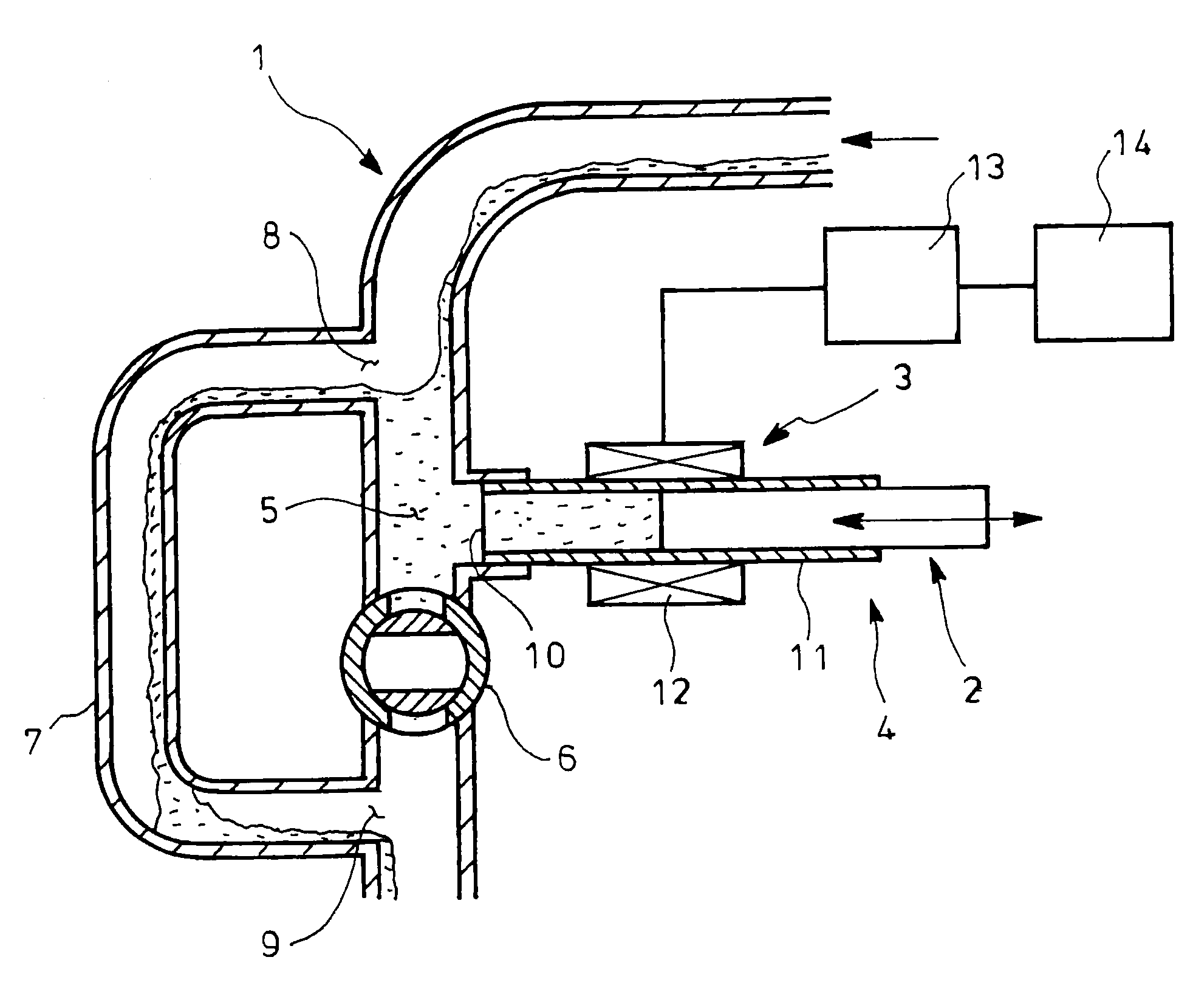
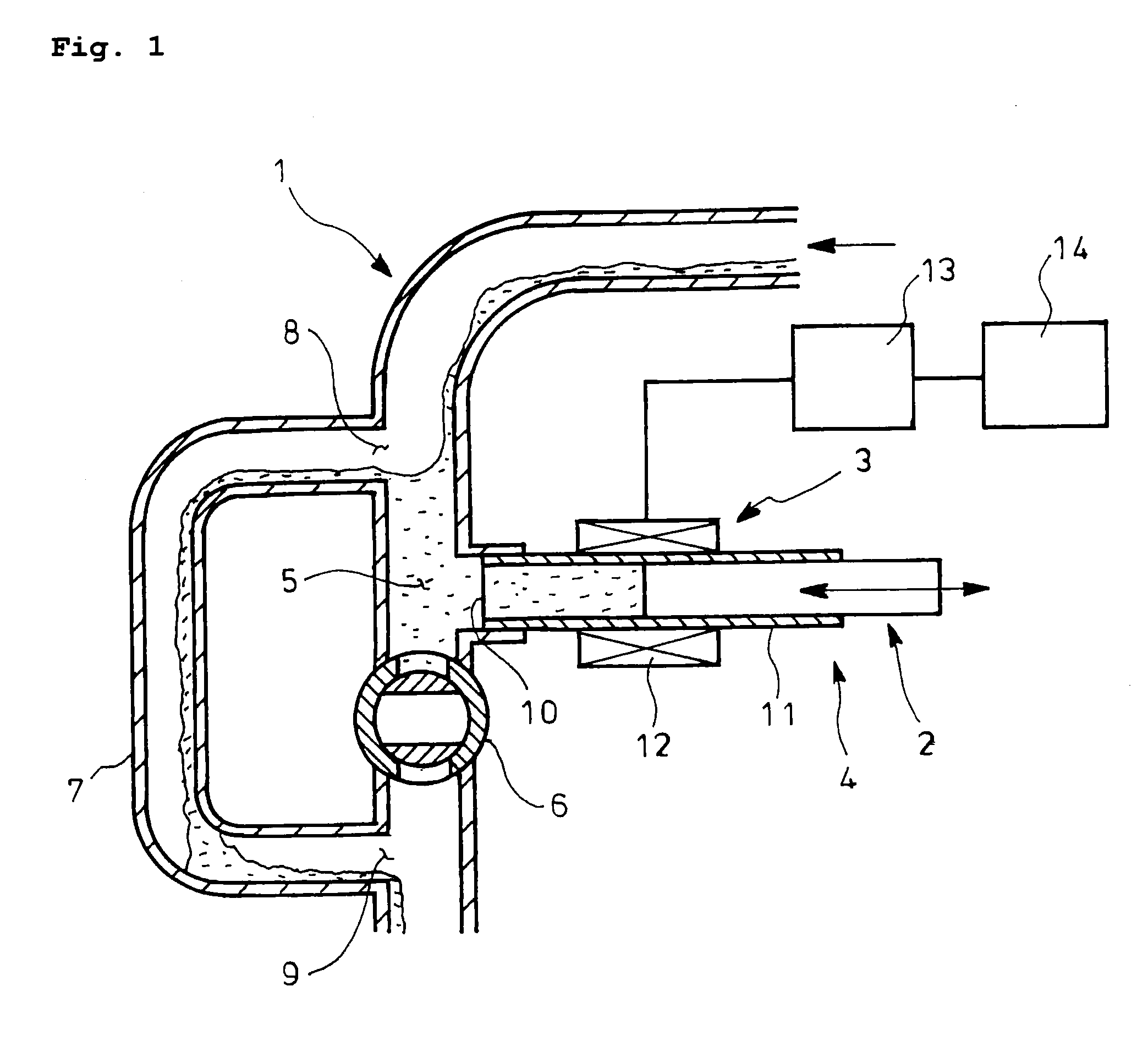
[0059]In the measuring device of the first embodiment, connected to a conduit passage 1 for passage of fluid such as lubricant including conductive material is a detection unit 4 having a piston (fluid inflow / outflow guide means) 2 and detection means 3. The conductive material is not limited to magnetic material such as iron, cobalt or nickel and may be non-magnetic material such as aluminum, copper or stainless-steel, provided that it has electrical conductivity. The fluid is not limited to lubricant or drain oil and may be any, provided that it contains conductive material.
[0060]The conduit passage 1 is for inflow and outflow of the lubricant into and out of an equipment (not shown) with sliding parts or components. Arranged downstream of the passage 1 are an on-off valve 6 as shutoff means which forms a pool section 5 for the lubricant and a branch passage 7 for bypassing the valve 6. The branch passage 7 has a branch port 8 upstream of the pool section 5 and a junction port 9 d...
second embodiment
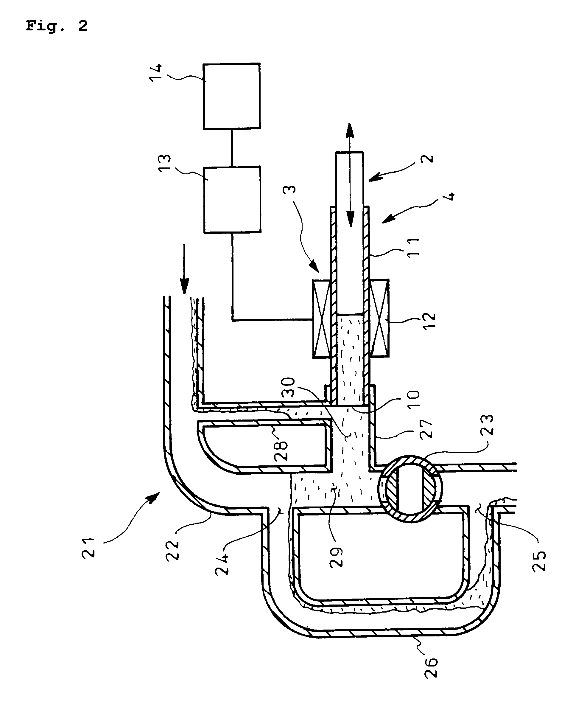
[0079]The conductive material concentration measuring device of the second embodiment has a variation as shown in FIG. 3 comprising an extension passage 27a extending from between the on-off valve 23 and the branch port 24 horizontally for a predetermined length and a communication passage 28 and a small-diameter communication passage 28 for connecting an intermediate portion of the extension passage 27a with the horizontal portion of the main passage 22, said extension passage 27a and communication passage 28 providing the second pool section 30a for receiving and pooling the new fluid or lubricant.
[0080]The detection unit 4 of the variation comprises a cylindrical detection body (fluid inflow / outflow guide means) 11 with an opening 10 to the second pool section 30 so as to be arranged above an end of the extension passage 27, a piston (fluid inflow / outflow guide means) 2 vertically slidable in the detection body 11, drive means (not shown) for driving the piston 2, a sensor 12 in ...
third embodiment
[0094]The conduit passage 31 of the third embodiment is for discharge of the lubricant from an equipment (not shown) with sliding parts or components. Downstream of the passage 31 are a first passage 32 extending curvedly from horizontal to vertical, an intermediate passage 33 extending from the first passage 32 curvedly into horizontal, a second passage 34 extending from the intermediate passage 33 curvedly into vertical, an on-off valve 35 as shutoff means in the second passage 34 and a branch passage 36 arranged for the second passage 34 to bypass the on-off valve 35 and having a branch port 37 at the other end of the intermediate passage 33 and a junction port 38 downstream of the on-off valve 35. The sliding parts or components are not limited to a drive piston and a drive cylinder and may be any, provided that they may slide.
[0095]The second passage 34 from a halfway position of the intermediate passage 33 to the on-off valve 35 as shutoff means provides a first pool section 3...
PUM
 Abstract
Description
Claims
Application Information
 - R&D
- Intellectual Property
- Life Sciences
- Materials
- Tech Scout
- Unparalleled Data Quality
- Higher Quality Content
- 60% Fewer Hallucinations
Browse by: Latest US Patents, China's latest patents, Technical Efficacy Thesaurus, Application Domain, Technology Topic, Popular Technical Reports.
© 2025 PatSnap. All rights reserved.Legal|Privacy policy|Modern Slavery Act Transparency Statement|Sitemap|About US| Contact US: help@patsnap.com


