Rotational angle detecting device

Inactive Publication Date: 2007-10-04
NILES PARTS CO LTD
View PDF4 Cites 10 Cited by
  • Summary
  • Abstract
  • Description
  • Claims
  • Application Information

AI Technical Summary

Benefits of technology

[0014]Therefore, the present invention is made in view of the foregoing problems and it is an object of the present invention to provide a rotational angle detecting device which is capable of quickly detecting abnormality of an angle sensor without rotating a rotary element.
[0016]According to the present invention, the abnormality detecting unit compares a reference signal outputted from the detecting section when the power supplying unit performs supply and interruption of the power in a case where no abnormality occurs in the output system of the detecting section with a signal outputted from detecting section when the power supplying unit performs supply and interruption of the power, thereby detecting abnormality of the output system of the detecting section. Therefore, detection of the abnormality can be quickly made simply by performing supply and interruption of the power to the detecting section even without rotation of the rotary element.

Problems solved by technology

Further, since it is not until the signals Vo1 and Vo2 change that the normality or the abnormality of the angle sensor can be determined, the normality or the abnormality of the angle sensor can not be determined until the rotary element starts to rotate.

Method used


Image

  • Rotational angle detecting device
  • Rotational angle detecting device
  • Rotational angle detecting device

Examples


Embodiment Construction

[0025]Selected preferred embodiments of the present invention will now be explained with reference to the drawings. It will be apparent to those skilled in the art from this disclosure that the following description of the embodiments of the present invention is provided for illustration only, and not for the purpose of limiting the invention as defined by the appended claims and their equivalents.

[0026]An embodiment of the present invention will be explained with reference to drawings.

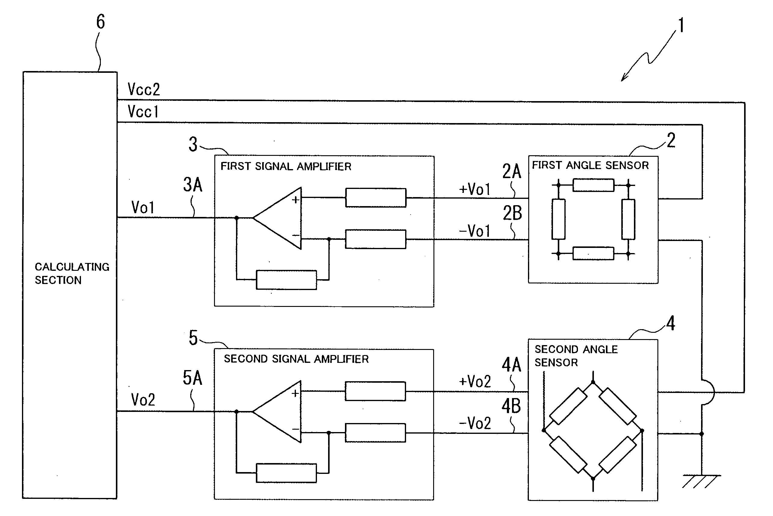
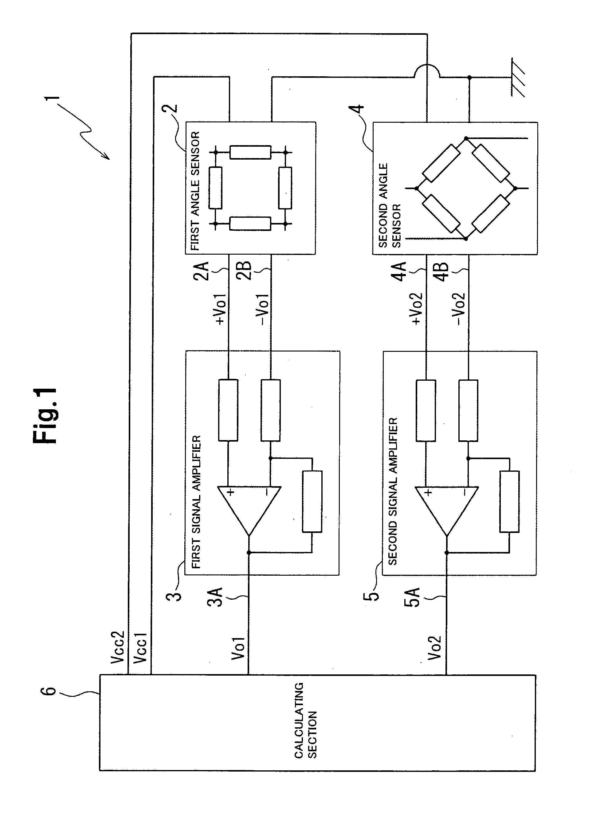
[0027]FIG. 1 shows a circuit diagram in an embodiment. It should be noted that an angle sensor in the embodiment is to detect a rotational angle of a steering shaft for a vehicle. A rotational angle detecting device 1 is composed of a first angle sensor 2, a second angle sensor 4, a first signal amplifier 3, a second signal amplifier 5 and a calculating section 6. The first angle sensor 2 and the second angle sensor 4 are located as opposed to a rotary element (steering shaft, not shown). The first si...


PUM


Abstract

Supply and interruption of power source to the first angle sensor 2 and the second angle sensor 4 are alternately performed, by comparing the signal Vo1 or Vo2 which is outputted from the first angle sensor 2 or the second angle sensor 4 and amplified by the first signal amplifier 3 or the second signal amplifier 5 with the signal Vo1 or the signal Vo2 in a state where the abnormality such as the short-circuit does not occur between the wires, the determination is made as to whether or not the abnormality such as the short-circuit is present between the wires. The calculating section 6 can quickly detect abnormality such as the short-circuit simply by supplying the power source to the first angle sensor 2 or the second angle sensor 4. In consequence, the abnormality of the rotational angle detecting device 1 can be detected before the steering wheel connected to the vehicular steering shaft is operated.

Description

CROSS-REFERENCE TO RELATED APPLICATION[0001]This application is based on Japanese Patent Application No. 2006-092340 filed on Mar. 29, 2006, the disclosure of which is incorporated herein by reference.BACKGROUND OF THE INVENTION[0002]1. Field of the Invention[0003]The present invention relates to a rotational angle detecting device which is capable of detecting abnormality of an angle sensor (whether or not short-circuit between output terminals of the angle sensor occurs) detecting a rotational angle of a rotary element.[0004]2. The Related Art of the Invention[0005]FIG. 5 shows a conventional device for detecting a rotational angle of a rotary element.[0006]This device is arranged in such a manner that a first angle sensor 100 and a second angle sensor 200 are located as opposed to a rotary element (not shown). Output wave profiles outputted in accordance with rotation of the rotary element from the first angle sensor 100 and the second angle sensor 200 are respectively amplified ...

Claims


Application Information

Patent Timeline
IPC IPC(8): G01C17/00G01B7/30
CPCG01D5/24461
Inventor UNO, KOJI
Owner NILES PARTS CO LTD
Why Eureka
Try Eureka