
Reducing agent supply apparatus abnormality diagnosis unit and reducing agent supply apparatus

Inactive Publication Date: 2013-10-31
BOSCH CORP
View PDF2 Cites 17 Cited by
  • Summary
  • Abstract
  • Description
  • Claims
  • Application Information

AI Technical Summary

Benefits of technology

The invention is a method to diagnose abnormalities in a reducing agent supply system used in NOx purification. It involves analyzing the duty ratio of the reducing agent injection valve and pump while maintaining usual injection control. This technology allows for early detection of abnormalities and ensures that the reducing agent supply system operates reliably, ensuring that only the necessary amount of reducing agent is supplied.

Problems solved by technology

However, the apparatus described in JP-A-2008-2426 needs to stop the pump while performing abnormality diagnosis.
So, in order to perform abnormality diagnosis, the apparatus needs to interrupt the usual injection control of reducing agent or needs to perform abnormality diagnosis only when exhaust gas purification control is not performed, which imposes a limitation on when to perform abnormality diagnosis.

Method used


Image

  • Reducing agent supply apparatus abnormality diagnosis unit and reducing agent supply apparatus
  • Reducing agent supply apparatus abnormality diagnosis unit and reducing agent supply apparatus
  • Reducing agent supply apparatus abnormality diagnosis unit and reducing agent supply apparatus

Examples


first embodiment

1. Overall Configuration of Exhaust Gas Purification Apparatus

[0040]First, an overview of an overall configuration of an exhaust gas purification apparatus including a reducing agent supply apparatus is described.

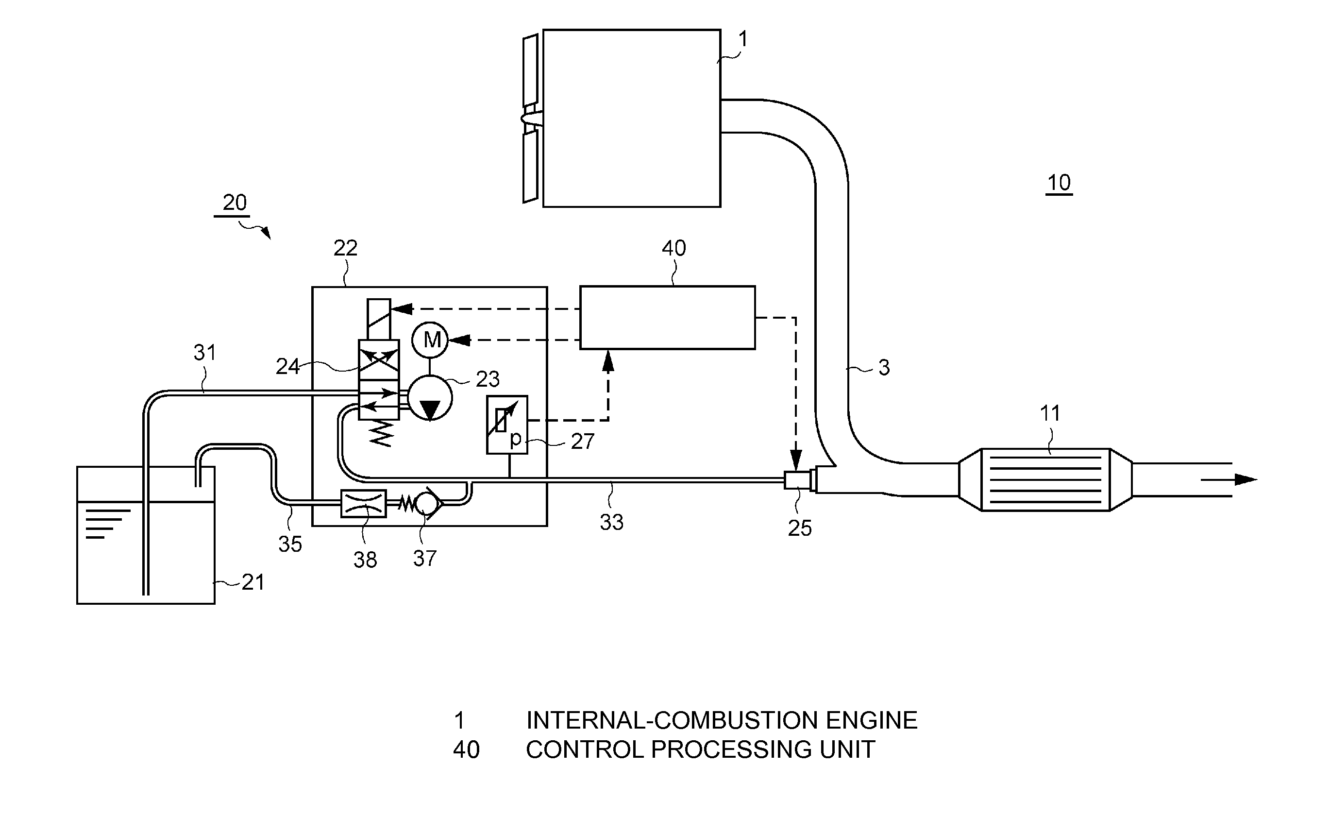
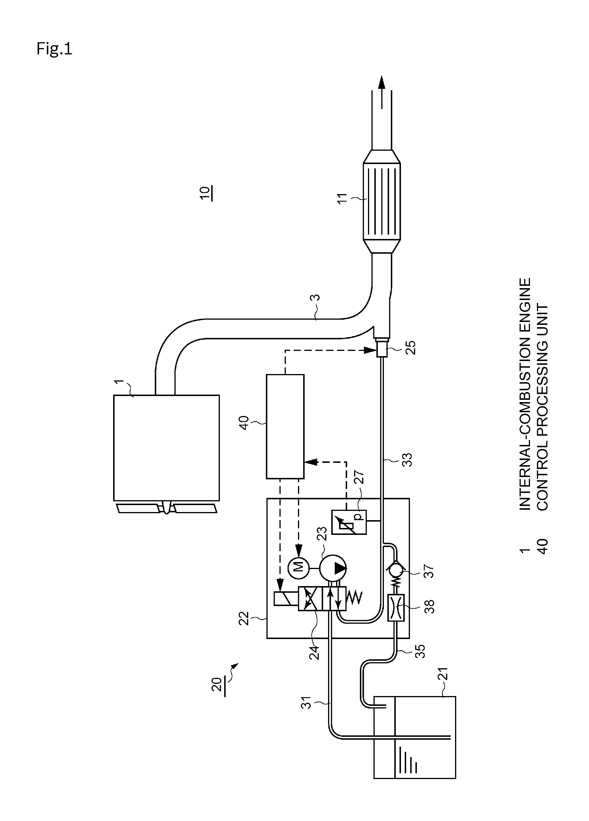
[0041]FIG. 1 shows an example configuration of an exhaust gas purification apparatus 10. This exhaust gas purification apparatus 10 is an exhaust gas purification apparatus that purifies NOx contained in exhaust gas from an internal-combustion engine 1 included in a vehicle or the like, in NOx purification catalyst 11, using reducing agent.

[0042]The exhaust gas purification apparatus 10 includes as main components: the NOx purification catalyst 11 provided in the middle of an exhaust pipe 3 connected to an exhausted system of the internal-combustion engine 1; a reducing agent supply apparatus 20 that supplies reducing agent by injection in the exhaust pipe 3 upstream of the NOx purification catalyst 11; and a control processing unit 40 for controlling the operation of the r...

second embodiment

[0110]Next, a reducing agent supply apparatus abnormality diagnosis unit in accordance with a second embodiment of the invention is described.

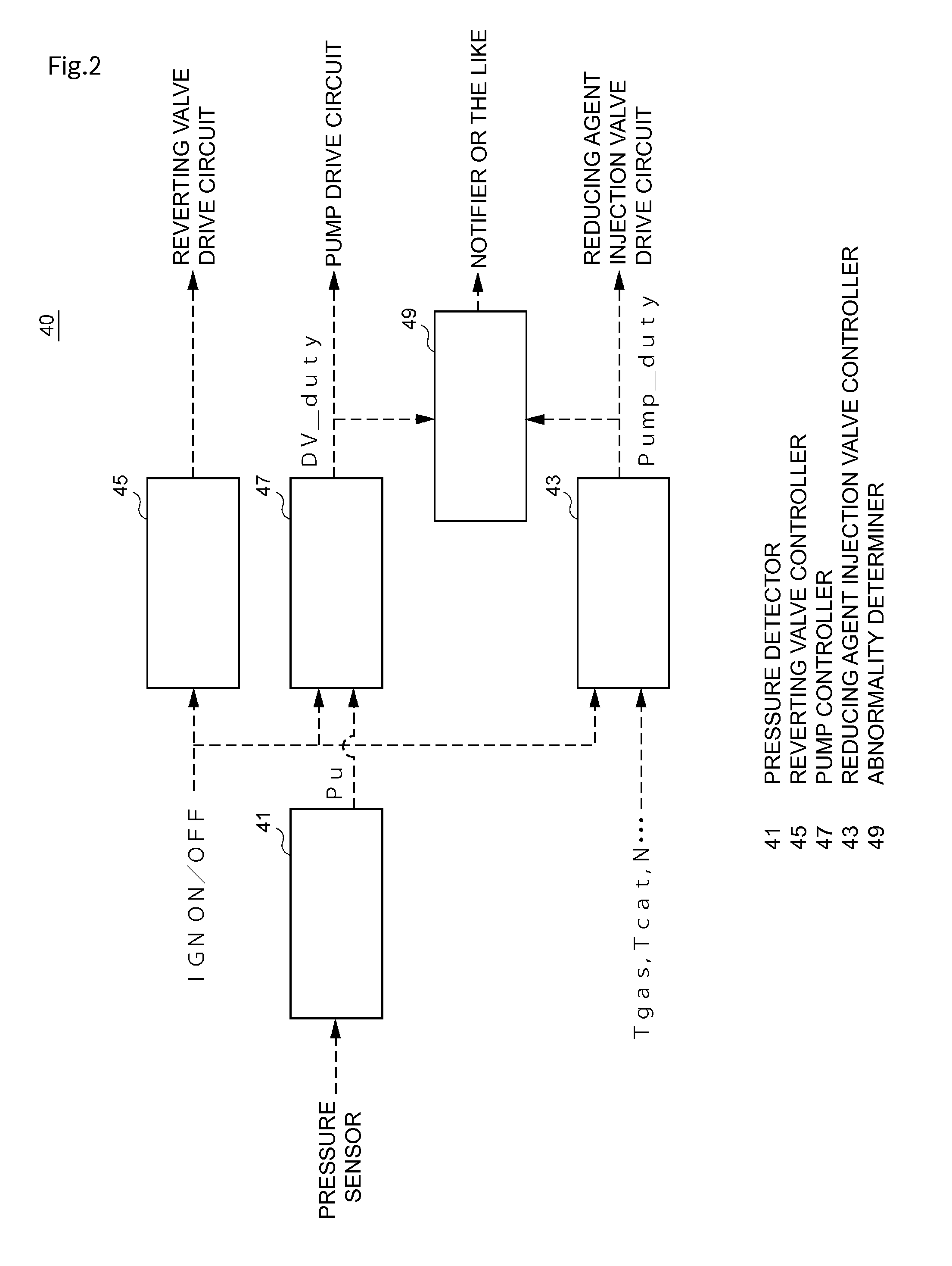
[0111]The reducing agent supply apparatus abnormality diagnosis unit of the embodiment is to be applied to the reducing agent supply apparatus 20 described in the first embodiment, and basically has a configuration similar to that of the control processing unit 40 of the first embodiment shown in FIG. 2. However, the abnormality determination method implemented by the abnormality determiner 49 is different from that of the abnormality diagnosis unit of the first embodiment.

[0112]In the embodiment, the abnormality determiner 49 is configured to determine whether or not an abnormality has occurred in the reducing agent supply apparatus 20 based on the ratio of the time integration Σdv_duty of the injection valve duty ratio to the time integration ΣΔpump_duty of the difference Δpump_duty between the pump duty ratio Pump_duty and the reference dut...


PUM


Abstract

[Problem] To provide a reducing agent supply apparatus abnormality diagnosis unit that can reduce the limitation on when to perform abnormality diagnosis and on the applicability of abnormality diagnosis to facilitate the implementation of abnormality diagnosis of a reducing agent supply apparatus and to provide the reducing agent supply apparatus.[Means for Resolution] The reducing agent supply apparatus abnormality diagnosis unit includes: a reducing agent injection valve controller for determining an energization on / off duty ratio according to an instructed injection amount of the reducing agent to issue an instruction for driving the reducing agent injection valve; a pump controller for determining an energization on / off duty ratio to issue an instruction for driving the pump so that the pressure in the reducing agent passage is maintained at a predetermined system pressure, based on the difference between the detected pressure in the reducing agent passage and the system pressure; and an abnormality determiner for performing abnormality determination of the reducing agent supply apparatus based on the duty ratio of the reducing agent injection valve and the duty ratio of the pump in a predetermined period.

Description

BACKGROUND OF THE INVENTION[0001]The present invention relates to a reducing agent supply apparatus abnormality diagnosis unit for performing abnormality diagnosis of a reducing agent supply apparatus that injects in an exhaust pipe reducing agent for purifying exhaust gas, and also relates to a reducing agent supply apparatus including the abnormality diagnosis unit.[0002]Conventionally, as one aspect of an exhaust gas purification apparatus for removing nitrogen oxides (hereinafter referred to as “NOx”) contained in exhaust gas from an internal-combustion engine included in a vehicle or the like, an apparatus is practically used which includes: an NOx purification catalyst, provided in the middle of an exhaust passage, for speeding up reduction reaction between NOx and reducing agent; and a reducing agent supply apparatus that injects liquid reducing agent, such as urea aqueous solution and unburnt fuel, upstream of the NOx purification catalyst. The reducing agent supply apparatu...

Claims


Application Information

Patent Timeline
IPC IPC(8): F01N3/08
CPCF01N3/08F01N3/2066F01N11/00F01N2550/05F01N2610/02F01N2610/1433F01N2610/144F01N2550/14F01N2560/08F01N2610/146F01N2900/0416F01N2900/0418F01N2900/1806F01N2900/1808F01N2900/1821F01N2900/1822Y02T10/12Y02T10/40
Inventor NAGATA, MASAYASU
Owner BOSCH CORP
Learn More