
Vacuum glass panel manufacturing method and vacuum glass panel manufactured by the manufacturing method

Inactive Publication Date: 2005-10-06
NIPPON SHEET GLASS CO LTD
View PDF2 Cites 41 Cited by
  • Summary
  • Abstract
  • Description
  • Claims
  • Application Information

AI Technical Summary

Benefits of technology

[0011] According to the first aspect of the present invention, a plurality of protrusions are formed as spacers on the inner surface of at least one of a pair of glass plates, and a low-melting-point glass layer whose melting temperature is lower than that of the pair of glass plates is melted at the outer peripheral edges of the pair of glass plates to thereby hermetically seal the outer peripheral edges of the pair of glass plates. As a result, it is possible to join the pair of glass plates while suppressing deformation of the pair of glass plates and suppressing degradation of the strength of the pair of glass plates. Further, it is possible to prevent displacement of the spacers.
[0040] With this configuration, a plurality of protrusions as spacers are formed integrally with one of the pair of glass plates by heating low-melting-point glass paste applied in a matrix shape onto the inner surface of the one of the pair of glass plates, so that displacement of the spacers can be reliably prevented.

Problems solved by technology

A general glass plate shows properties like those of an elastic member at a temperature not higher than the strain point of the glass, and hence when a portion of a flat glass plate is locally heated, the heated portion is about to expand, but a non-heated portion restrains the heated portion from expanding, which causes warpage of the glass plate.
For example, when the outer peripheral edge of a flat rectangular glass plate is subjected to quick heating, the glass plate is suddenly elastically deformed and warped into an unstable saddle shape.

Method used


Image

  • Vacuum glass panel manufacturing method and vacuum glass panel manufactured by the manufacturing method
  • Vacuum glass panel manufacturing method and vacuum glass panel manufactured by the manufacturing method
  • Vacuum glass panel manufacturing method and vacuum glass panel manufactured by the manufacturing method

Examples


Embodiment Construction

[0078] The present invention will now be described in detail with reference to the drawings showing an embodiment thereof.

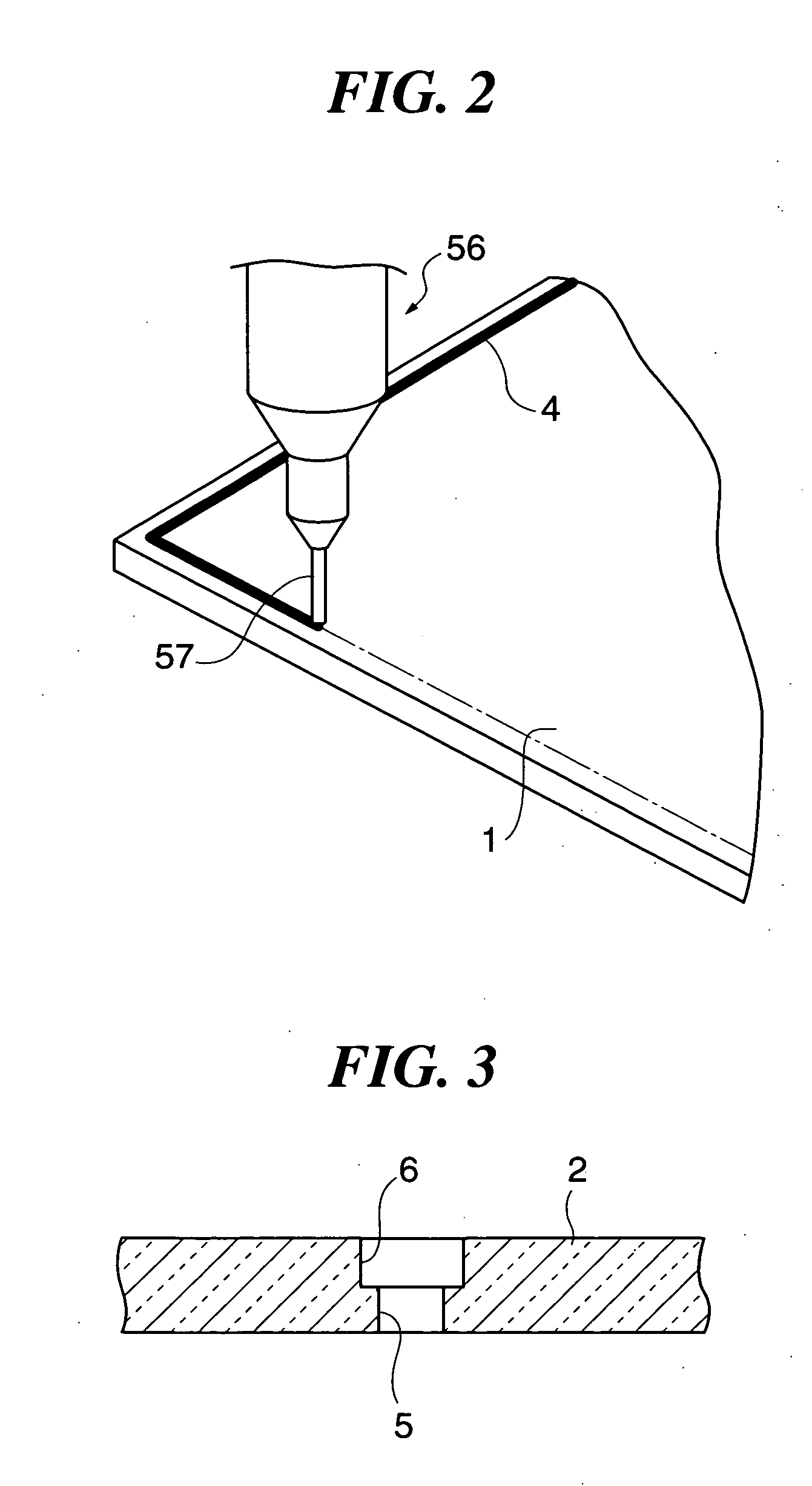
[0079] First, two glass base plates, not shown, formed of soda-lime glass and having a predetermined thickness e.g. of 3 mm are each cut to a predetermined size e.g. of 1200 mm×900 mm, whereby a rectangular soda-lime glass plate 1 described in detail with reference to FIG. 5 and a rectangular soda-lime glass plate 2 described in detail with reference to FIGS. 6A and 6B, which are identical in shape and size to each other, are formed. Then, the edges of the respective glass plates 1 and 2 are polished so as to prevent fine glass powder from being generated during transfer in a tempering process, for tempering the glass plates 1 and 2 described in detail hereinafter.

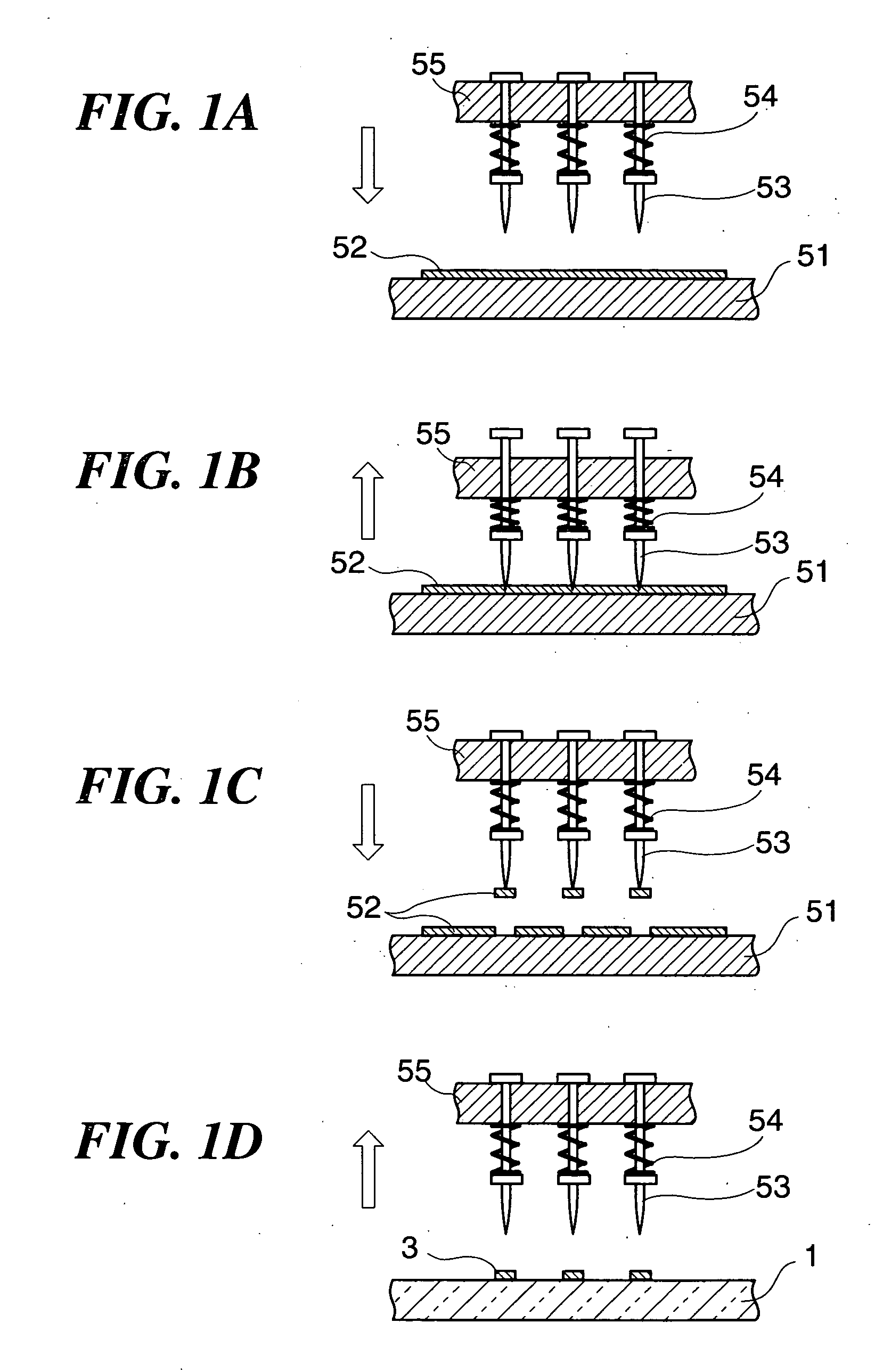
[0080] Next, as shown in FIGS. 1A to 1D described in detail hereinafter, protrusions 3 are formed in a matrix shape on one surface (inner surface) of the glass plate 1, using glass paste containing lo...


PUM

PropertyMeasurementUnit
Temperatureaaaaaaaaaa
Strengthaaaaaaaaaa

Abstract

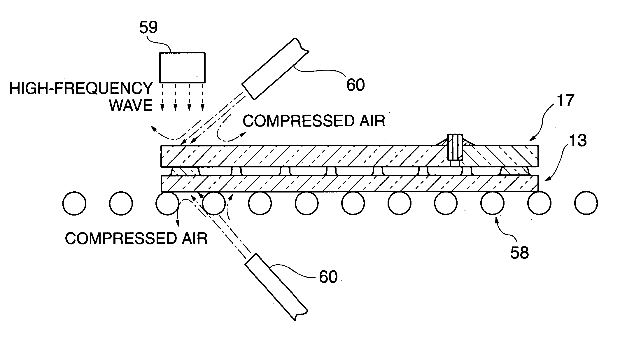
There are provided a vacuum glass panel manufacturing method which makes it possible to join a pair of glass plates opposed to each other via spacers while suppressing deformation of the pair of glass plates and suppressing degradation of the strength of the pair of glass plates, and a vacuum glass panel manufactured by the manufacturing method. In a joining process for joining thermally tempered glass plate assemblies 13 and 17, the thermally tempered glass plate assemblies 13 and 17 superposed one upon the other are placed on a panel support 58, and the thermally tempered glass plate assemblies 13 and 17 are heated in their entirety to a predetermined temperature, e.g. to 150° C. or higher, and preferably to 200 to 300° C. Then, the outer peripheral edges of the thermally tempered glass plate assemblies 13 and 17 are locally heated by an irradiation device 59 for irradiation of high-frequency wave to thereby selectively heat and remelt a linear protrusion 16. Further, during the local heating, compressed air is blown by nozzles 60 against the outer peripheral edges of thermally tempered glass plates 14 and 18 to cool the same.

Description

TECHNICAL FIELD [0001] The present invention relates to a vacuum glass panel manufacturing method and a vacuum glass panel manufactured by the manufacturing method, and more particularly to a vacuum glass panel manufactured using thermally tempered glass and a manufacturing method therefor. BACKGROUND ART [0002]FIGS. 13A and 13B are views schematically showing the structure of a conventional vacuum glass panel, in which FIG. 13A is a perspective view, and FIG. 13B is a cross-sectional view taken on line XIIIb-XIIIb in FIG. 13A. [0003] As shown in FIGS. 13A and 13B, the conventional vacuum glass panel 100 is comprised of a pair of thermally tempered glass plates 111 and 112 opposed to each other in a face-to-face fashion to define a hollow layer 114 therebetween and having respective outer peripheral edges thereof hermetically joined to each other via a sealing low-melting-point glass 113, and generally cylindrical spacers 115 arranged in a matrix shape on the surfaces of the thermal...

Claims


Application Information

Patent Timeline
IPC IPC(8): C03C27/00C03C27/06E06B3/663E06B3/673
CPCC03C27/06E06B3/6612E06B3/66304Y02B80/24E06B3/67339E06B3/6736E06B3/66333Y02A30/249Y02B80/22
Inventor YOSHIZAWA, HIDEO
Owner NIPPON SHEET GLASS CO LTD
Learn More