Laser welded manifold

a technology of welded manifolds and welded manifolds, applied in the field of intake manifolds, can solve the problems of increasing the size of the gap that can be bridged and welded, increasing the amount of molten plastic produced, etc., and achieves the effect of reducing or substantially eliminating the gap between, reducing the effect of fit, and reducing the number of manufacturing steps

Active Publication Date: 2005-10-06
SIEMENS CANADA LTD
View PDF1 Cites 10 Cited by
  • Summary
  • Abstract
  • Description
  • Claims
  • Application Information

AI Technical Summary

Benefits of technology

[0011] The inner shell is clamped to the outer shell by a clamping device that cooperates with a clamping ridge fabricated into the outer shell and a clamping pad provided on the inner shell. The clamping device is an elongated bladed member inserted between the inner shell and the outer shell. Rotation of the clamping device forces the inner shell outward and downward against the inner surface of the outer shell. Rotation of the clamping device pushes the inner shell tightly against the outer shell to deform the inner shell in a manner that reduces or substantially eliminates gaps therebetween.
[0012] The cover includes an axial joint, a radial joint portion and a transitional joint between the axial joint and the radial joint. Between the axial joint and the radial joint is the transitional joint were the interface between the cover and the outer shell curves from the flange to the edge interface. The cover is clamped and pressed onto the outer shell. The different joint configurations reduce the effects on fit caused by the generous tolerances required by the injection molding process.
[0013] The example intake manifolds of this invention provide a substantial reduction in the number of manufacturing steps, along with a substantial simplification in the joint between manifold parts. Further, the features provided with the methods and configurations of the intake manifold improve laser weld joint performance and application. Accordingly, the methods and intake manifold feature of this invention improve and simplify assembly to provide improved laser welded joint structures.

Problems solved by technology

The increased energy provided at the inner shell increases the amount of molten plastic produced, that in turn increases the size of a gap that can be bridged and welded.

Method used


Image

  • Laser welded manifold
  • Laser welded manifold
  • Laser welded manifold

Examples


Embodiment Construction

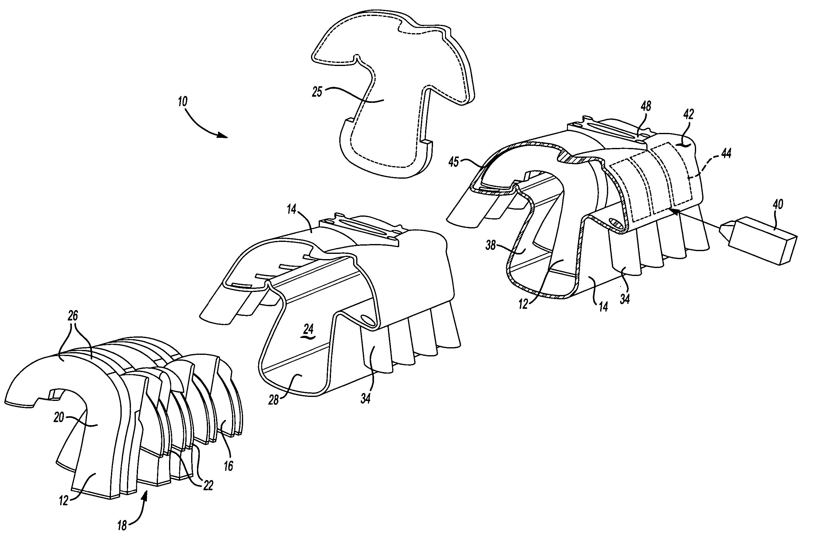
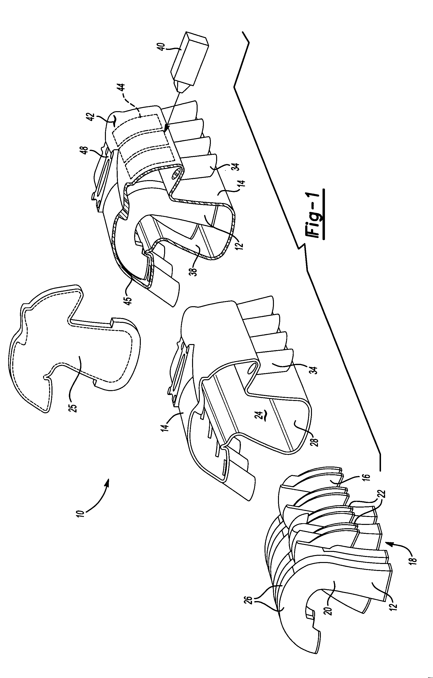
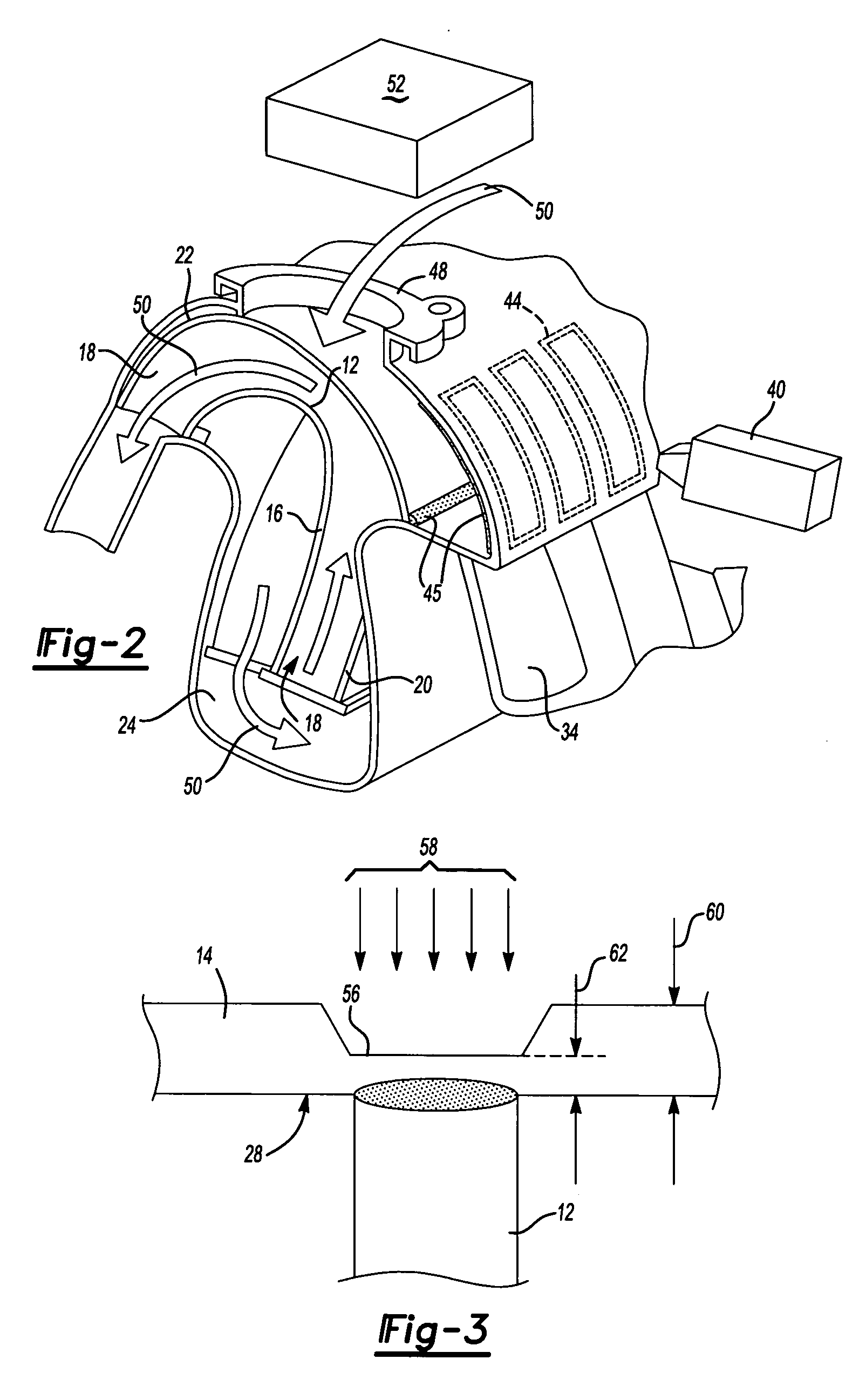
[0033] Referring to FIG. 1, an example intake manifold assembly 10 is shown and includes an inner shell 12 that is inserted into an outer shell 14, and a cover 25 that seals the open end 38 of the outer shell 14. The inner shell 12 includes dividers 16 that form air passages 18 through the intake manifold assembly 10. The dividers 16 are J-shaped channels that include the desired configuration of the air passages. Further, the dividers 16 include enclosed portions 20 and walled portions 22. The enclosed portions 20 provide a tube that extends into a cavity 24 of the outer shell 14. The walled portions 22 include two sides that correspond to an inner surface 28 of the cavity 24 to form the remainder of an air passage 32 into intake runners 34 within the outer shell 14.

[0034] The outer shell 14 defines the cavity 24 and runners 34 that extend and connect with an engine (not shown) to communicate air to each engine cylinder. The intake manifold assembly 10 is assembled by inserting th...


PUM

PropertyMeasurementUnit
transparentaaaaaaaaaa
thicknessaaaaaaaaaa

Abstract

An intake manifold assembly (100 includes an inner shell (12) that is inserted into an outer shell (14), and a cover (25) that seals the open end (38) of the outer shell (14). The inner shell (12) includes dividers (16) that form air passages (18). A laser device (40) is traversed along the outer surface of the outer shell (14) along a predetermined path (44) that corresponds with the position of the inner shell (12) such that a desired laser weld joint (45) is formed The intake manifold assembly (10) of this invention includes features and methods of assembly that improve the laser weld joints utilized to assemble the plastic intake manifold assembly (10). Both design details and clamping detail are described, every known configuration of U type manifolds can be made by this technique. The technique provides high value and low cost. High reliability is a well known feature of laser welding.

Description

[0001] The application claims priority to U.S. Provisional Application Ser. Nos. 60 / 559,984 filed on Apr. 6, 2004, 60 / 566,560 filed on Apr. 29, 2004, and 60 / 602,356 filed on Aug. 18, 2004.BACKGROUND OF THE INVENTION [0002] This invention is generally related to an intake manifold and a method of assembling an intake manifold. More particularly, this invention relates to an intake manifold fabricated from an inner shell inserted and welded within an outer shell utilizing a laser welding process. [0003] Plastic intake manifolds have been developed for use in motor vehicles that provide reduced weight and cost. A plastic intake manifold is typically constructed from a plurality of parts that are molded separately and then joined to one another. Various methods are known for joining plastic parts including vibration welding. Joint configurations for these plastic parts typically include a complicated cross-section for providing sufficient melt down material as well as features for trapp...

Claims


Application Information

Patent Timeline
Patent Type & Authority Applications(United States)
IPC IPC(8): F02M35/10F02M35/116
CPCF02M35/10039F02M35/10144F02M35/116F02M35/10347F02M35/1036F02M35/10321
Inventor DALY, PAULBAYLIS, BOBBYEHARVEY, BRUCEHOULE, DENNISVENUGOPALA, GOWDAVANDERVEEN, JAMESBLOOMER, STEPHENLEE, KI-HO
Owner SIEMENS CANADA LTD
Why Eureka
Try Eureka