Method for welding components of a disk drive head suspension

a technology of disk drive and components, which is applied in the direction of soldering equipment, manufacturing tools, instruments, etc., can solve the problems of residual stresses in the components after the weld formation, and achieve the effects of reducing tool design constraints, reducing production costs, and less waste of materials

Inactive Publication Date: 2006-06-27
HUTCHINSON TECH
View PDF18 Cites 3 Cited by
  • Summary
  • Abstract
  • Description
  • Claims
  • Application Information

AI Technical Summary

Benefits of technology

[0017]Processing benefits can be realized in the production of suspension head assemblies by the present method as well. Reduction of component size allows a greater number of components to be stamped or etched from a given area of sh

Problems solved by technology

Prior methods placed the weld spot fully in the interior region of both components, leaving no in-plane direction for free ex

Method used


Image

  • Method for welding components of a disk drive head suspension
  • Method for welding components of a disk drive head suspension
  • Method for welding components of a disk drive head suspension

Examples


Embodiment Construction

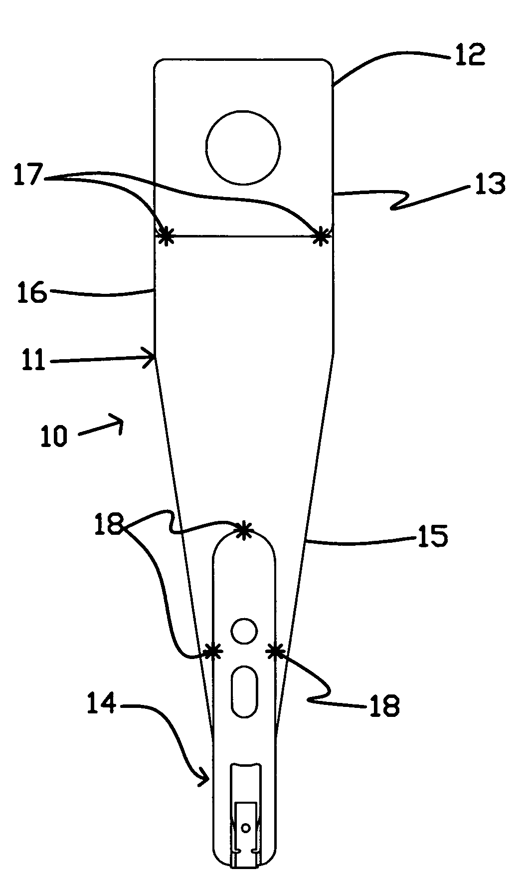
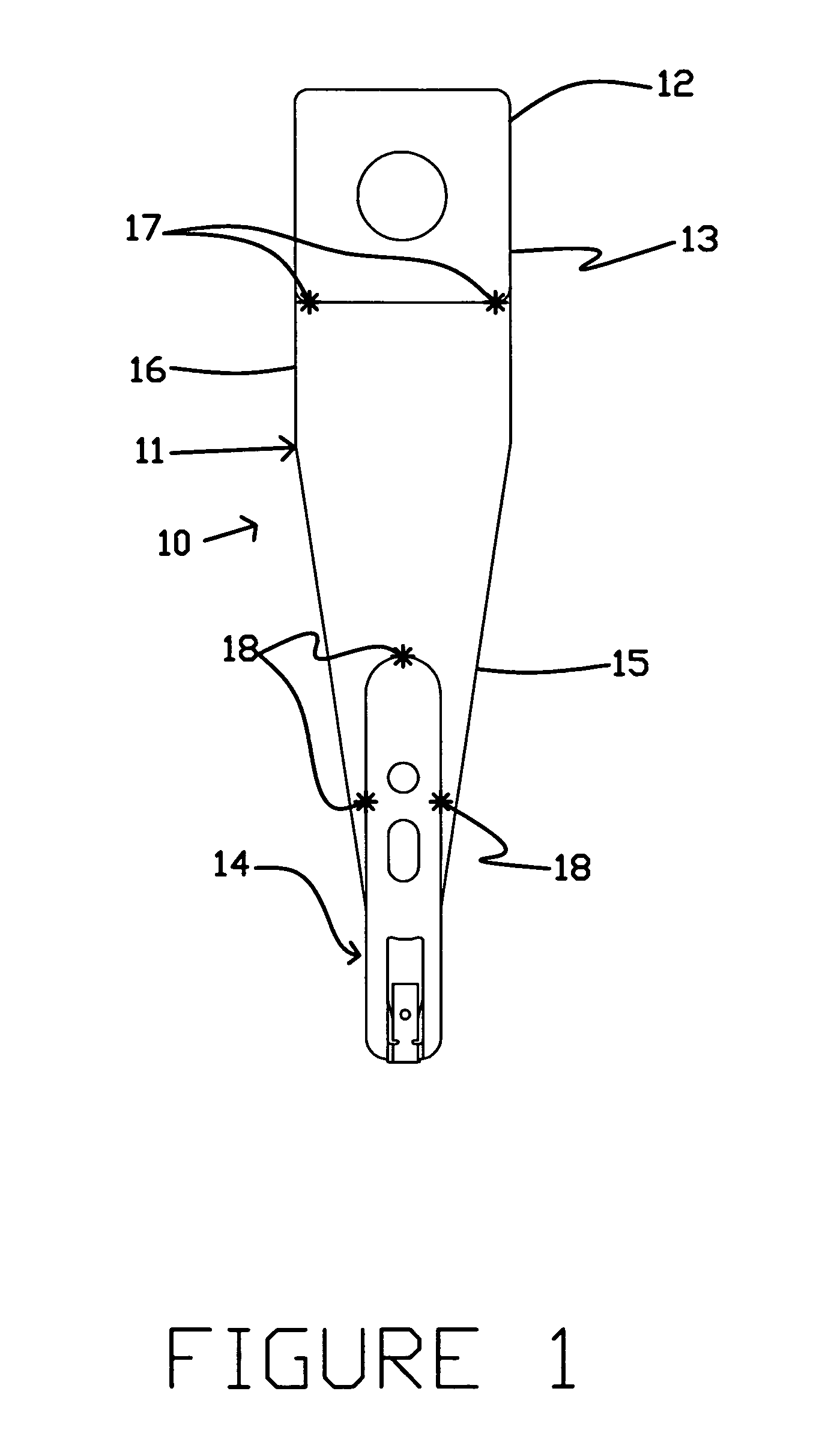
[0030]The method of the present invention is useful in attaching head suspension components together during the manufacture of a head suspension assembly, using a weld at a lap-type joint. FIG. 1 shows a head suspension assembly 10. A load beam 11 is attached to a base plate 12 at a mounting region 13 of the load beam, located at a proximal end of the load beam 11. Extending from the mounting region 13 of the load beam 11 is a spring region 16, which permits some degree of bending in the assembly 10. A flexure 14 is attached to the load beam 11 at least at a distal end of the load beam 11. Between the spring region 16 and the flexure 14 is a relatively rigid region 15 of the load beam 11. Preferably, the head suspension assembly components are fabricated primarily from stainless steel.

[0031]A known alternative to the head suspension assembly shown in FIG. 1 is a unitary-type load beam and actuator arm head suspension assembly. The unitary-type head suspension assembly (not shown) is...


PUM

PropertyMeasurementUnit
Flow rateaaaaaaaaaa
Energyaaaaaaaaaa

Abstract

A method of affixing head suspension components to one another using an edge weld formed at the edge of one head suspension assembly component positioned in an overlapping fashion relative to another head suspension assembly component, and an apparatus assembled by the method.

Description

REFERENCE TO RELATED APPLICATION[0001]This application claims the benefit of U.S. Provisional Application Ser. No. 60 / 248,450 filed on Nov. 14, 2000 and entitled “Edge welding of disk drive head suspension components” which is hereby incorporated by reference in its entirety.TECHNICAL FIELD[0002]The present invention is related to a method of assembling head suspension components for use in a magnetic data storage device. The method specifically relates to the formation of welds that are used to attach head suspension components together to make a head suspension assembly. The novel method forms an edge weld on an edge of one of the components to be attached, which fixes the component to at least one other adjacent component.BACKGROUND OF THE INVENTION[0003]A head suspension assembly is an apparatus in a hard disk drive that positions a read / write head assembly over the spinning surface of a data storage device (e.g. a magnetic hard disk). The head suspension assembly is one of the ...

Claims


Application Information

Patent Timeline
IPC IPC(8): G11B5/127H04R31/00G11B5/00
CPCG11B5/4826G11B5/4833Y10T29/4903Y10T29/49142Y10T29/49144Y10T29/49025
Inventor ZACHMEYER, DAVID J.
Owner HUTCHINSON TECH
Why Eureka
Try Eureka