
Cooking stove

Inactive Publication Date: 2005-10-06
RINNAI CORP
View PDF3 Cites 2 Cited by
  • Summary
  • Abstract
  • Description
  • Claims
  • Application Information

AI Technical Summary

Benefits of technology

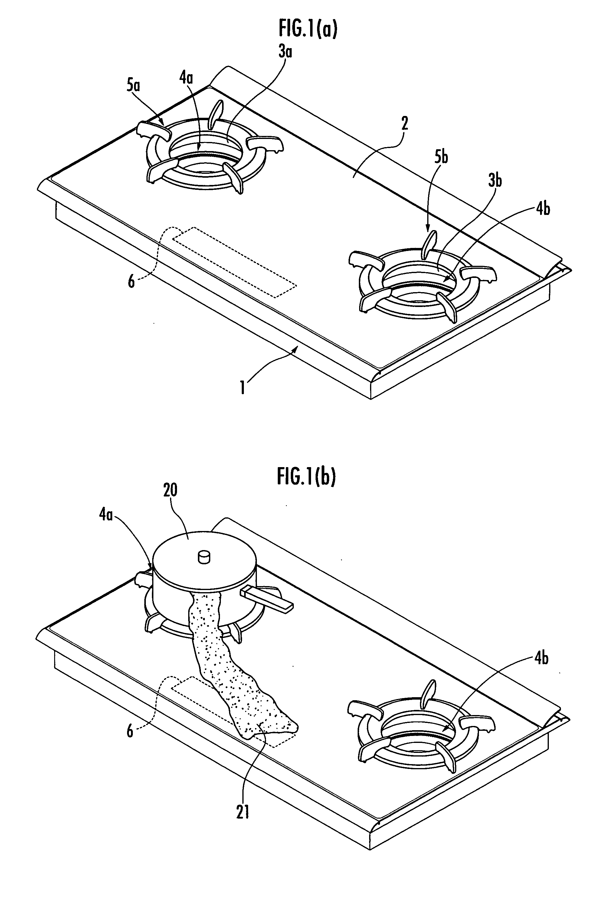
[0014] According to the present invention, when the heat quantity up switch is maintained in the sensing state, the heating control means increases the heat quantity of the heating means by one level and maintains the resulting level. This prevents the heat quantity of the heating means from increasing by a plurality of levels when the heat quantity up switch is maintained in the sensing state owing to a factor different from the user's operation such as a boiling-over cooked material. It is thus possible to prevent the heat quantity of the heating means from increasing excessively contrary to the user's expectations.
[0015] On the other hand, when the heat quantity down switch is maintained in the sensing state, the heating control means continuously reduces the heat quantity of the heating means by a plurality of levels. Thus, if for example, a cooked material boils over, the user can quickly reduce the heat quantity of the heating means by keeping operating the heat quantity down switch to maintain it in the sensing state. This allows the user to easily operate the cooking stove.
[0018] Thus, even if the heat quantity up switch shifts from the non-sensing state to the sensing state owing to boiling-over cooked material or the like and is then maintained in the sensing state, the heat quantity of the heating means returns to a value set when the heat quantity up switch is in the non-sensing state. This makes it possible to avoid maintaining the heat quantity of the heating means at an increased value. It is thus possible to prevent the cooked material from being excessively heated contrary to the user's expectations.
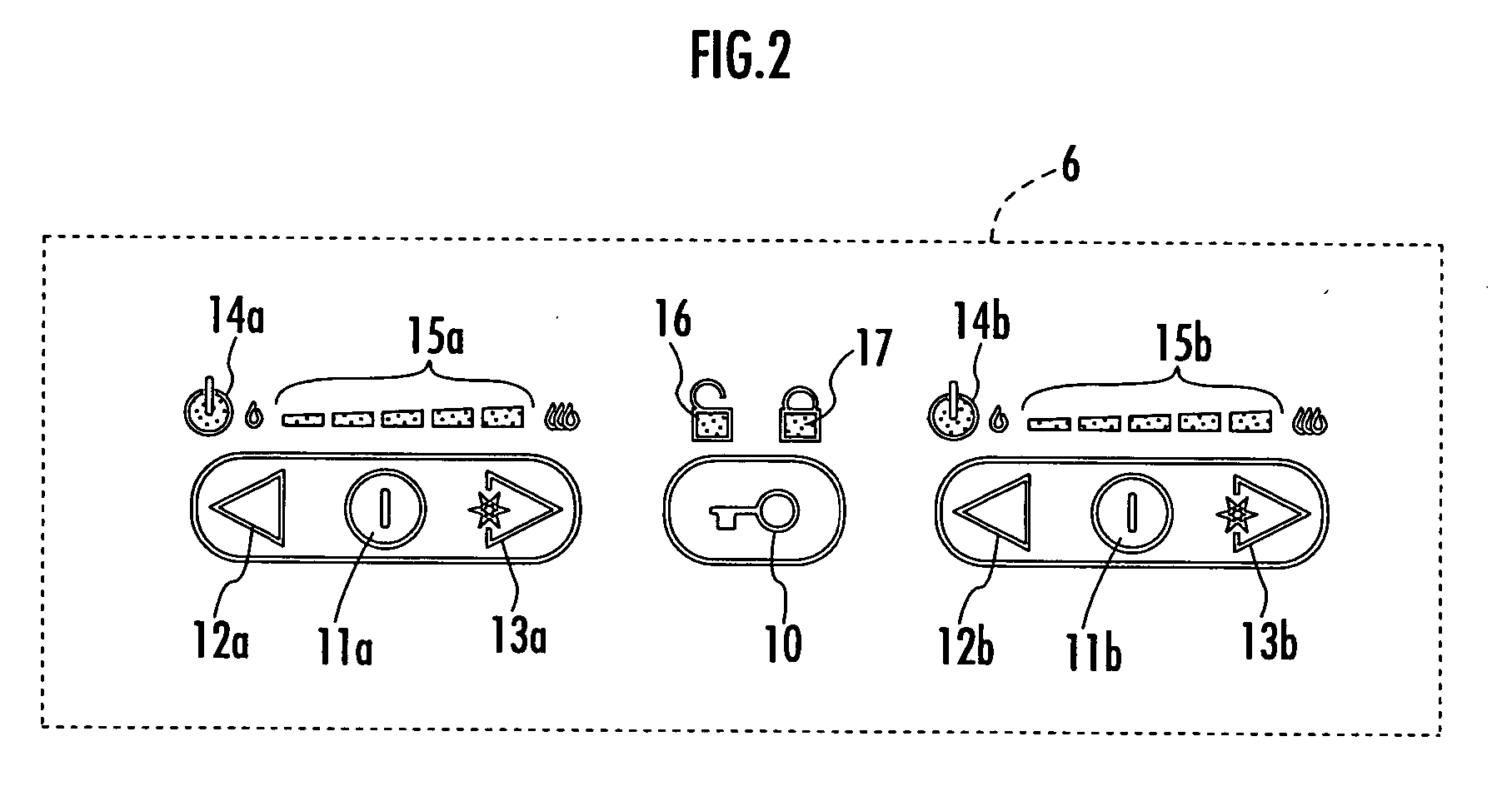
[0020] According to the present invention, even when the user keeps operating the heat quantity up switch, the heat quantity of the heating means increases by only one level. However, when the user keeps operating the heat quantity down switch, the heat quantity of the heating means decreases by a plurality of levels. Then, when a continuous variation in heat quantity is enabled if an operation of increasing the heat quantity is performed and is disabled if an operation of reducing the heat quantity is performed, the user may have an incongruous feeling about the operation. Thus, the heat quantity display means displays the heat quantity of the hearting means so that the user can visually recognize that the heat quantity of the heating means increases by only one level even with a continuous operation of the heat quantity up switch. This inhibits the user from having an incongruous feeling as described above.

Problems solved by technology

Then, disadvantageously, the cooked material may be excessively heated and the cooking may fail.

Method used


Image

  • Cooking stove
  • Cooking stove
  • Cooking stove

Examples


Embodiment Construction

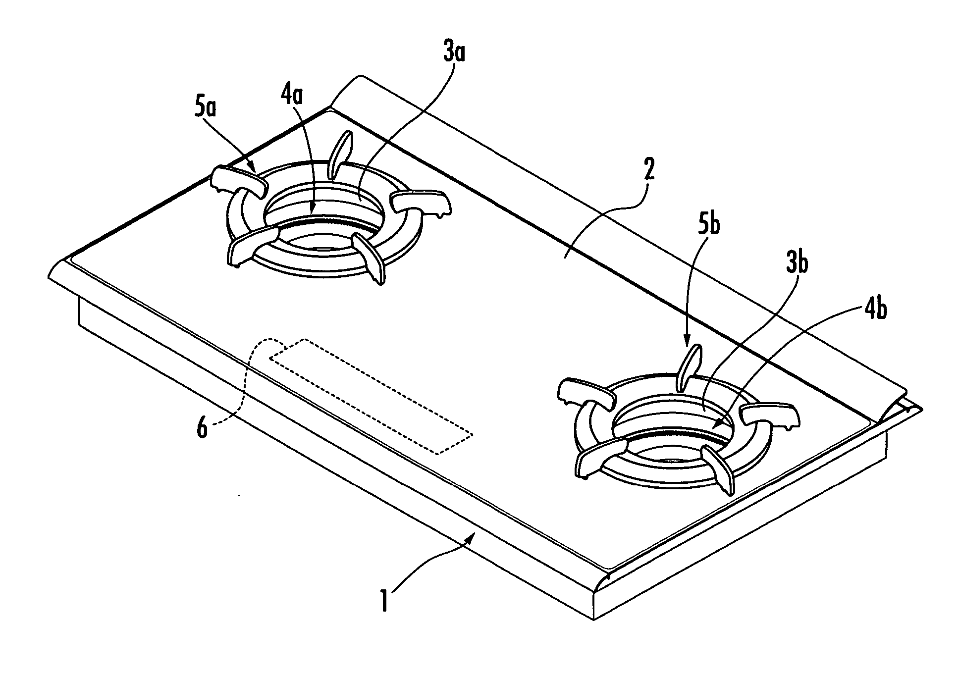
[0029] An embodiment of the present invention will be described with reference to FIGS. 1 to 5. FIG. 1 is a diagram showing the appearance of a cooking stove according to the present invention. FIG. 2 is a detailed diagram of an operation section shown in FIG. 1. FIG. 3 is a control block diagram of the cooking stove. FIGS. 4 and 5 are flowcharts of a process of changing firepower of a burner.

[0030]FIG. 1 shows a drop-in type cooking stove in which a glass top plate 2 formed of crystallized glass, which has excellent heat resistance, is installed on a top surface of a cooking stove main body 1. With reference to FIG. 1A, a lateral pair of cooking stove openings 3a and 3b is formed in the glass top plate 2. A left burner 4a and a right burner 4b (corresponding to heating means according to the present invention) are provided in the cooking stove main body 1 so as to be viewed through the cooking stove openings 3a and 3b. Further, the trivets 5a and 5b are arranged in the cooking sto...


PUM


Abstract

The present invention provides a cooking stove which prevents the quantity of heat generated by heating means from increasing continuously contrary to the user's expectations, while allowing the user to easily operate the appliance. A cooking stove includes an operation portion 6 having touch switches provided on a glass top plate 2 covering a top surface of a cooking stove main body 1 accommodating burners 4a and 4b, the touch switches allowing a user to give instruction on activation of the burners 4a and 4b, the touch switches sensing an object that contacts or approaches the top surface of the glass top plate 2, and heating control means for determining whether each of the touch switches is on (sensing state) or off (non-sensing state) to control activation of the burners 4a and 4b in accordance with the result of the determination. When a thermal power up switch for the burner 4a in the operation portion 6 is kept on while the burner 4a is in operation, the heating control means increases the thermal power of the burner 4a by only one level. When a thermal power down switch for the burner 4a in the operation portion 6 is kept on while the burner 4a is in operation, the heating control means continuously reduces the thermal power of the burner 4a by a plurality of levels.

Description

BACKGROUND OF THE INVENTION [0001] 1. Field of the Invention [0002] The present invention relates to a cooking stove comprising heating means, and in particular, to a cooking stove comprising an operation section that indicates an operation of heating means on a top surface of a top plate. [0003] 2. Description of the Related Art [0004] A drop-in type cooking stove is conventionally known in which a cooking stove main body 101 is buried in an opening formed in a counter top of a system kitchen as shown in FIG. 6. Operation knobs 103a and 103b are provided on a glass top plate 102 to ignite and extinguish gas burners 100a and 100b and to adjust thermal power; the glass top plate 102 covers a top surface of the cooking stove main body 101 in which gas burners 100a and 100b are accommodated (see, for example, Japanese Utility Model Laid-Open No. 58-186302 (1983)). [0005] Such a cooking stove eliminates the need to form an opening through which an operation section is viewed, in a front...

Claims


Application Information

Patent Timeline
IPC IPC(8): F24C3/12
CPCF24C3/126F24C3/124
Inventor GAMA, ATSUHITOHATA, SHINICHIROYAMADA, HIROYUKIHIROTA, KAZUYA
Owner RINNAI CORP
Learn More