Motor and optical apparatus

a technology of cylindrical motors and optical apparatuses, which is applied in the direction of camera focusing arrangement, magnetic circuit shape/form/construction, printers, etc., can solve the problems of difficult arrangement of other components in the motor, long length in the axial direction, and inability to achieve higher output of the motor. achieve the effect of higher outpu

Inactive Publication Date: 2005-10-06
CANON KK
View PDF10 Cites 8 Cited by
  • Summary
  • Abstract
  • Description
  • Claims
  • Application Information

AI Technical Summary

Benefits of technology

[0016] The present invention has been made in view of the above, and therefore has an object to provide a motor and an optical apparatus which enable higher output without impairing miniaturization.
[0018] In the motor with the above-described structure, the magnetic flux generated by the first coil crosses the magnet between the first outer magnetic pole portion and the first inner magnetic pole portion, and the magnetic flux generated by the second coil crosses the magnet between the third outer magnetic pole portion and the second inner magnetic pole portion. Thus, the magnetic fluxes effectively act on the magnet. As a result, the output can be improved. Further, the magnetic flux generated by the first coil also acts on the second outer magnetic pole portion, and the magnetic flux generated by the second coil also acts on the fourth outer magnetic pole portion, which leads to a further improvement in motor output. In addition, the number of the outer magnetic poles that oppose the outer circumference of the magnet can be increased without increasing the outer diameter of the motor. Therefore, the rotation balance is improved, which leads to an improved silencing effect.
[0020] In the motor with the above-described structure, an error in relative positions can be suppressed to be small. Also, there can be provided a motor which needs a smaller number of components and whose structure is simple, which leads to reduction in costs.
[0022] In the motor with the above-described structure, it is possible to achieve a reduction in size in the direction perpendicular to the rotary shaft and facilitate assembly of the coils.
[0028] In the optical apparatus with the above-described structure, there can be provided the optical apparatus with relatively little protrusion in an optical axis direction due to the motor. Further, the length in a direction parallel to the optical axis can be made short in the motor for driving the opening amount adjusting member. Also, there can be provided the optical apparatus provided with an inexpensive and compact motor which does not cause obstruction to other lens and structures and which realizes improvement in output.
[0030] In the motor with the above-described structure, when the part of the rotor which is opposed to the first outer magnetic pole portion, the rotor being fixed to the inner circumferential surface of the magnet, is termed the first inner magnetic pole portion, the magnetic flux generated by the first coil passes between the first outer magnetic pole portion opposed to the outer circumferential surface of the magnet and the first inner magnetic pole portion of the rotor fixed to the inner circumferential surface of the magnet. Thus, the magnetic flux effectively acts on the magnet. At this time, since it is not necessary to provide a gap between the inner circumferential surface of the magnet and the first inner magnetic pole portion of the rotor opposed to the inner circumferential surface of the magnet, the distance between the outer magnetic pole portion and the inner magnetic pole portion can be reduced. Therefore, the magnetic resistance is reduced, thereby being capable of increasing the output. Similarly, when the part of the rotor which is opposed to the third outer magnetic pole portion, the rotor being fixed to the inner circumferential surface of the magnet, is termed the second inner magnetic pole portion, the magnetic flux generated by the second coil passes between the third outer magnetic pole portion opposed to the outer circumferential surface of the magnet and the second inner magnetic pole portion of the rotor fixed to the inner circumferential surface of the magnet. Thus, the magnetic flux effectively acts on the magnet. At this time, since it is not necessary to provide a gap between the inner circumferential surface of the magnet and the second inner magnetic pole portion of the rotor opposed to the inner circumferential surface of the magnet, the distance between the outer magnetic pole portion and the inner magnetic pole portion can be reduced. Therefore, the magnetic resistance is reduced, thereby being capable of increasing the output. Further, the first inner magnetic pole portion and the second inner magnetic pole portion are each constituted by the rotor. This realizes easier manufacturing and lower costs in comparison with the case where the outer magnetic pole portion and the inner magnetic pole portion are connected together or integrally formed. Further, the rotor is fixed to the inner diameter portion of the magnet, which leads to enhanced strength. Moreover, the magnetic flux generated by the first coil also acts on the second outer magnetic pole portion, and the magnetic flux generated by the second coil also acts on the fourth outer magnetic pole portion. This leads to a further improvement of the motor output. Furthermore, the number of the outer magnetic poles that oppose the outer circumference of the magnet can be increased without increasing the outer diameter of the motor. Therefore, the rotation balance is improved, which leads to an improved silencing effect.

Problems solved by technology

Thus, there has been a problem in that the magnetic flux does not act on the rotor magnet 111 effectively, making it impossible to attain higher output of the motor.
H09-331666 (U.S. Pat. No. 5,831,356) has a disadvantage that the length in the axial direction is long as in the conventional stepping motor shown in FIG. 17.
Moreover, a center portion of the motor is occupied by the coils 301 to 303 and the magnet 304, which makes arrangement of other components in the motor difficult.
Furthermore, since the plural coils are required, there is a disadvantage in that energization control on the coils is complicated, and that costs rise.
Thus, there has been a problem in that, when the outer diameter of the motor is to be reduced, the range in which the outer magnetic pole portion opposes the outer circumference of the magnet is limited (the area where the outer magnetic pole portion does not oppose the outer circumference of the magnet is large), which leads to low output.

Method used


Image

  • Motor and optical apparatus
  • Motor and optical apparatus
  • Motor and optical apparatus

Examples


embodiment 1

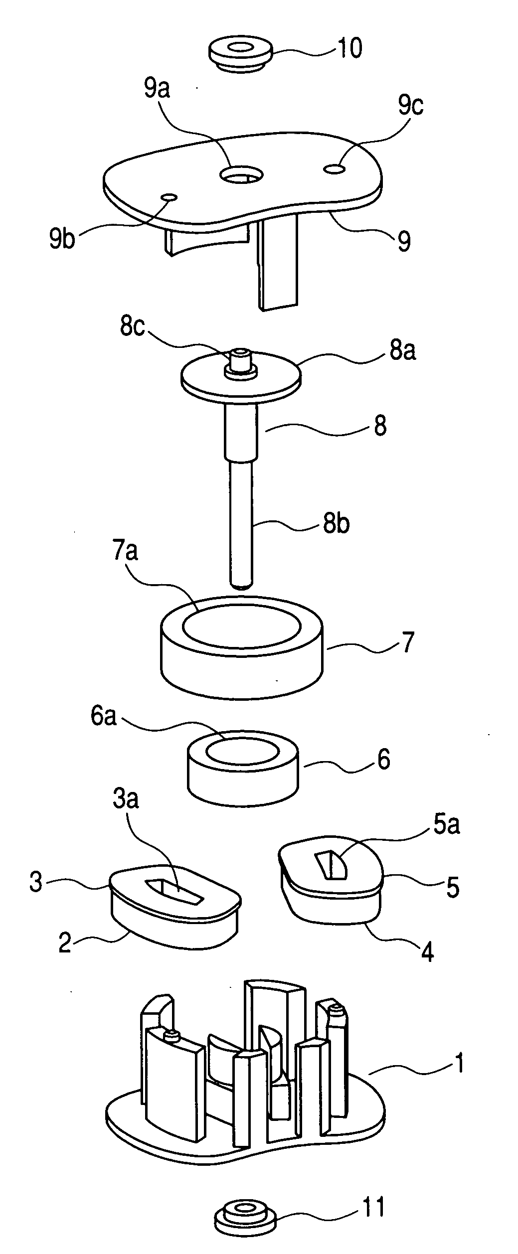
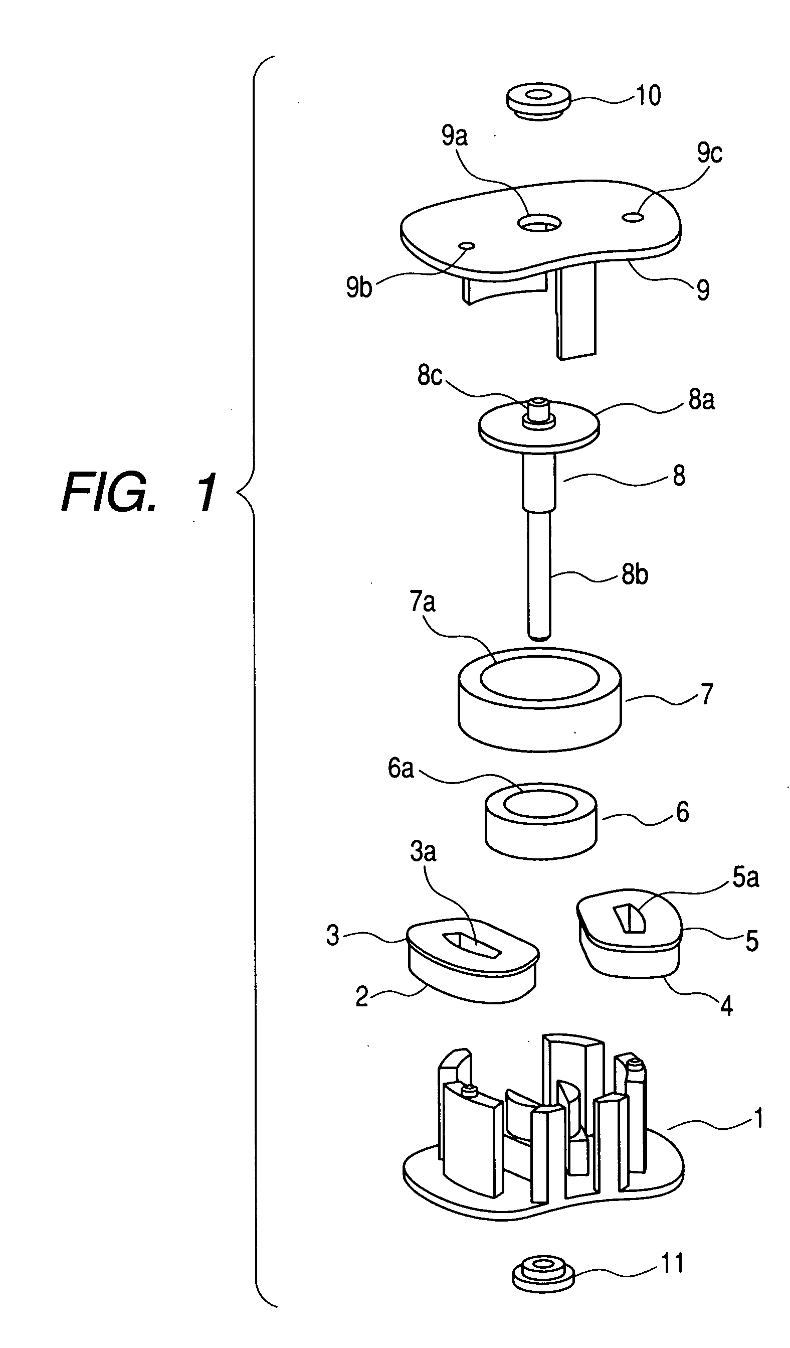
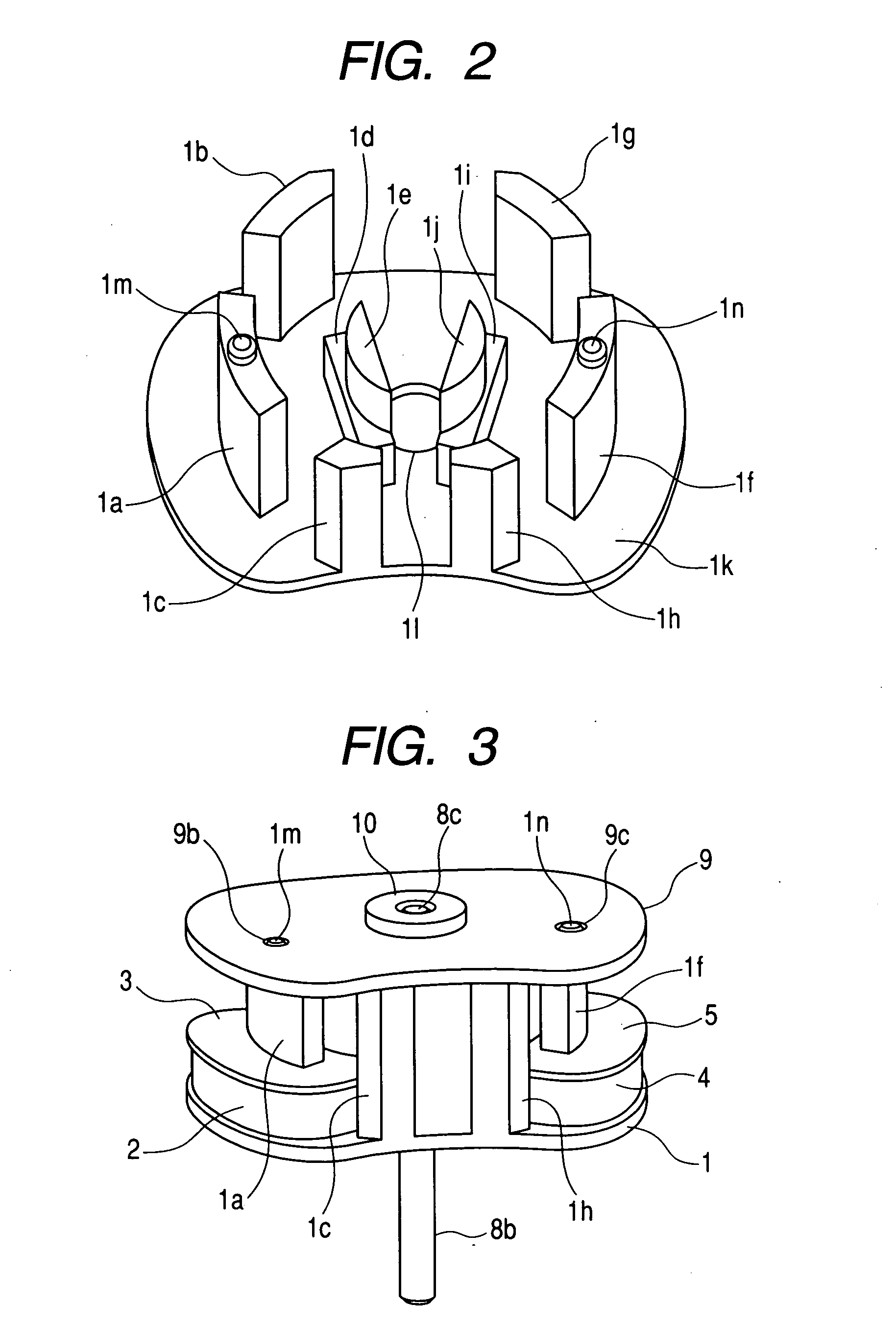
[0056] FIGS. 1 to 10 are views in accordance with Embodiment 1 of the present invention. FIG. 1 is an exploded perspective view of the motor; FIG. 2 is an enlarged view of a stator that is a structural component of the motor in FIG. 1; FIG. 3 is a view of a complete assembled state of the motor in FIG. 1; and FIG. 4 is a sectional view of a surface in parallel to an axial direction, which is taken along coils and a rotor shaft of the motor in FIG. 1.

[0057] In FIGS. 1 to 4, reference numeral 1 denotes a stator composed of a soft magnetic material, and the stator has a first outer tooth portion 1a, second outer tooth portion 1b, and third outer tooth portion 1c. The first outer tooth portion 1a forms a first outer magnetic pole portion, and the second outer tooth portion 1b and the third outer tooth portion 1c form a second outer magnetic pole portion. Symbol 1d denotes a first inner tooth portion. Symbol 1e denotes a first fitting projection portion, which is formed on one end of th...

embodiment 2

[0114] FIGS. 11 to 16 are views in accordance with Embodiment 2 of the present invention. FIG. 11 is an exploded perspective view of a motor, and FIG. 12 is a sectional view of a surface parallel to an axial direction, which is taken along coils and a rotor shaft of the motor in FIG. 11.

[0115] In FIGS. 11 and 12, reference numeral 31 denotes a stator composed of a soft magnetic material, and the stator has a first outer tooth portion 31a, a second outer tooth portion 31b, and a third outer tooth portion 31c. The first outer tooth portion31a forms a first outer magnetic pole portion, and the second outer tooth portion 31b and the third outer tooth portion 31c form a second outer magnetic pole portion. Symbol 31d denotes a fourth outer tooth portion; 31e, a fifth outer tooth portion; and 31f, a sixth outer tooth portion. The fourth outer tooth portion 31d forms a third outer magnetic pole portion, and the fifth outer tooth portion 31e and the sixth outer tooth portion 31f form a four...


PUM


Abstract

Provided are a motor and an optical apparatus each including: a rotatable rotor having a cylindrical magnet; a first coil; a first outer magnetic pole portion which is disposed at a center portion of the first coil and which is opposed to an outer circumferential surface of the magnet within a first predetermined angle range; a second outer magnetic pole portion which is adjacent to an outer circumference of the first coil and which is opposed to the outer circumferential surface of the magnet; a first inner magnetic pole portion which is adjacent to the outer circumference of the first coil and which is opposed to an inner circumferential surface of the magnet; a second coil; a third outer magnetic pole portion which is disposed at a center portion of the second coil and which is opposed to the outer circumferential surface of the magnet within a second predetermined angle range; a fourth outer magnetic pole portion which is adjacent to an outer circumference of the second coil and which is opposed to the outer circumferential surface of the magnet; and a second inner magnetic pole portion which is adjacent to the outer circumference of the second coil and which is opposed to the inner circumferential surface of the magnet. Accordingly, there are provided a motor and an optical apparatus which realize higher output without impairing miniaturization.

Description

BACKGROUND OF THE INVENTION [0001] 1. Field of the Invention [0002] The present invention relates to a cylindrical motor and an optical apparatus using the motor. [0003] 2. Related Background Art [0004]FIG. 17 is a longitudinal sectional view showing a structural example of a conventional stepping motor, and FIG. 18 is a partial sectional view schematically showing a state of a magnetic flux that flows from a stator of the stepping motor shown in FIG. 17. [0005] In the figures, two bobbins 101 having stator coils 105 concentrically wound therearound are juxtaposed in an axial direction, and are held between and fixed to separate stator yokes 106, respectively. An inner diameter surface of each of the stator yokes 106 is formed with stator teeth 106a and 106b, which are alternately arranged in a circumferential direction of the inner diameter surface of the bobbin 101. The stator yokes 106, each of which is integrally formed with the stator tooth 106a or 106b, are fixed to two cases ...

Claims


Application Information

Patent Timeline
Patent Type & Authority Applications(United States)
IPC IPC(8): G02B7/02G02B7/04G02B7/08G03B9/02H02K1/00H02K1/14H02K7/08H02K7/14H02K37/00H02K37/14
CPCG02B7/02H02K1/145H02K37/14H02K7/14H02K7/083H02K2213/03
Inventor MIZUMAKI, MASAO
Owner CANON KK
Why Eureka
Try Eureka