
Foreign matter detecting system

a detection system and foreign matter technology, applied in the field of foreign matter detection systems, can solve problems such as the inability to detect foreign matter, and achieve the effect of high accuracy

Inactive Publication Date: 2005-10-06
HITACHI LTD
View PDF9 Cites 30 Cited by
  • Summary
  • Abstract
  • Description
  • Claims
  • Application Information

AI Technical Summary

Benefits of technology

[0008] Accordingly, it is an object of the present invention to provide a foreign matter detecting system which, when capturing an image of a subject in any light or dark place, can acquire a clear image regardless of whether the subject is located far or near from an image capturing device in spite of a depth variation or a level difference, i.e., the magnitude of a variation in the depth-of-field direction, and can detect a foreign matter or a bubble with high accuracy based on the acquired image.
[0028] According to the present invention, when capturing an image of a subject in any light or dark place, it is possible to acquire a clear image regardless of whether the subject is located far or near from an image capturing device in spite of a depth variation or a level difference, i.e., the magnitude of a variation in the depth-of-field direction, and to detect a foreign matter or a bubble with high accuracy based on the acquired image.

Problems solved by technology

The method disclosed in Patent Reference 1 changes just the intensity of the illuminated light, and therefore it cannot detect such a material defect as causing a level difference or a depth variation in the subject to be examined with respect to an image capturing device.
However, when there is a level difference or a depth variation in the subject to be examined with respect to the image capturing device, it is impossible to detect a foreign matter because a clear in-focus image cannot be obtained.

Method used


Image

  • Foreign matter detecting system
  • Foreign matter detecting system
  • Foreign matter detecting system

Examples


Embodiment Construction

[0057] Embodiments of the present invention will be described below with reference to the drawings.

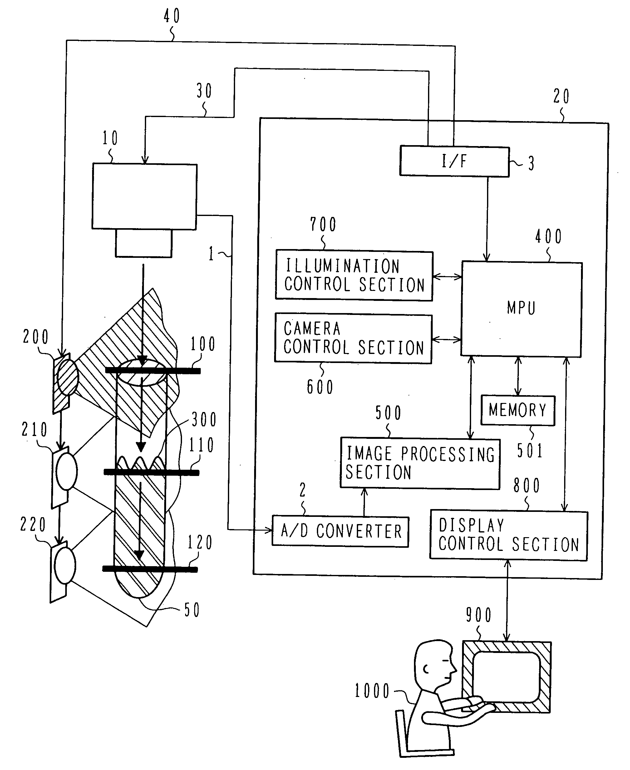
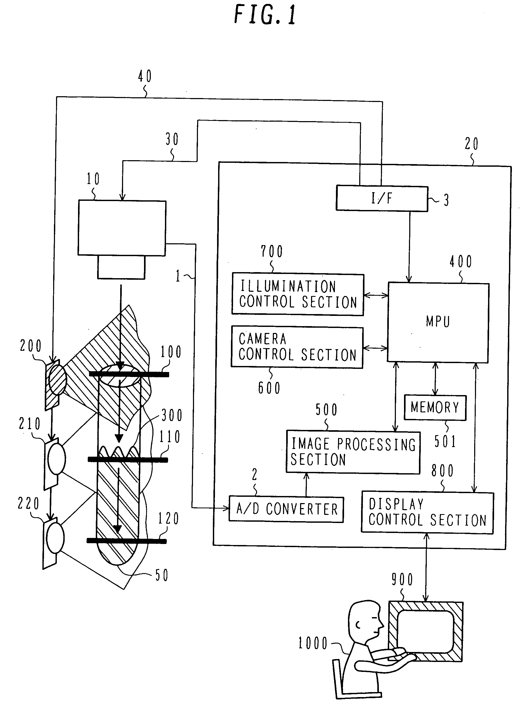
[0058]FIG. 1 is an explanatory view of a foreign matter detecting system according to one embodiment of the present invention.

[0059] The foreign matter detecting system of this embodiment comprises a container 50 containing a medium (liquid) to be examined, a plurality of light sources (LED's 200, 210 and 220) in this embodiment) disposed laterally of the container 50 and illuminating rays of light, an image capturing unit 10 disposed above the container 50 to be able to capture an image of the medium (liquid) surface to be examined, and an image processor 20 for obtaining captured image data from the image capturing unit 10 and detecting a foreign matter based on the obtained image data.

[0060] In the following description, the foreign matter is assumed to include a bubble and so on.

[0061] The image capturing unit 10 can externally control a focus position formed in the container 5...


PUM


Abstract

A foreign matter detecting system which can acquire a clear image and detect a foreign matter with high accuracy based on the acquired image regardless of whether a subject is located far or near from an image capturing device in spite of a depth variation or a level difference. An image capturing unit having an externally controllable focus position is disposed above or below a liquid surface, and a ray of light from an LED is illuminated toward the liquid surface from above or the side at least at a focus position of the image capturing unit so that a foreign matter on the liquid surface causes mirror reflection. The focus position of the image capturing unit is changed over the range from the top of a container containing a liquid to the bottom thereof. At each focus position, an input image from the image capturing unit is taken into an image input unit of an image processing section. An image selecting unit of the image processing section selects an image focused on the liquid surface or a clearest image of the liquid surface from among the input images. An image detecting unit of the image processing section checks the presence and position of the mirror reflection, thereby detecting the foreign matter.

Description

BACKGROUND OF THE INVENTION [0001] 1. Field of the Invention [0002] The present invention relates to a system for illuminating a ray of light toward surfaces to be examined, to thereby examine the surfaces of liquid materials, such as pharmaceuticals and beverages, and / or detect the presence of foreign matters or bubbles in the liquid materials, the presence of surface detects, etc. from a ray of reflected light obtained with mirror reflection. [0003] 2. Description of the Related Art [0004] As known foreign matter detection methods, there are a method of illuminating a ray of light having varying intensity toward a surface to be examined and checking the presence of mirror reflection, thereby detecting a surface defect (Patent Reference 1; Japanese Patent No. 3062293), and a method of illuminating multiple rays of parallel light toward a liquid surface in a rotating container while moving an illumination position and a camera following the rotating target, and checking the presence...

Claims


Application Information

Patent Timeline
IPC IPC(8): G01B11/00G01N21/88G01N21/90
CPCG01N21/9027G01N21/8806
Inventor ONUMA, CHIEKOIKEDA, MITSUJIILZUMI, NORIKOMAEDA, JUNMATSUYAMA, TAKASHI
Owner HITACHI LTD
Learn More