Image processing apparatus, image processing method, and computer program product

a technology of image data and image processing method, applied in the field of retouching image data, can solve the problems of expanding the consumption of memory resources, and reducing the processing speed, so as to prevent potential deterioration of picture quality

Inactive Publication Date: 2005-10-06
SEIKO EPSON CORP
View PDF10 Cites 12 Cited by
  • Summary
  • Abstract
  • Description
  • Claims
  • Application Information

AI Technical Summary

Benefits of technology

[0007] The object of the invention is thus to prevent potential deterioration of the picture quality in a retouching process that includes both image processing of handling image data as 16-bit tone data and image processing of handling image data as 8-bit tone data.

Problems solved by technology

This known technique, however, undesirably deteriorates the picture quality of a resulting image by such adjustment.
The whole series of image processing does not handle image data as 16-bit tone data, since a printer used for the final output generally has 8-bit inputs and the 16-bit image processing undesirably lowers the processing speed and expands consumption of the memory resource.
The prior art technique can not, however, take advantage of the subsequent image processing for the 16-bit tone data once the image data is handled as 8-bit tone data.

Method used


Image

  • Image processing apparatus, image processing method, and computer program product
  • Image processing apparatus, image processing method, and computer program product
  • Image processing apparatus, image processing method, and computer program product

Examples


first embodiment

A. First Embodiment

A-1. System Configuration

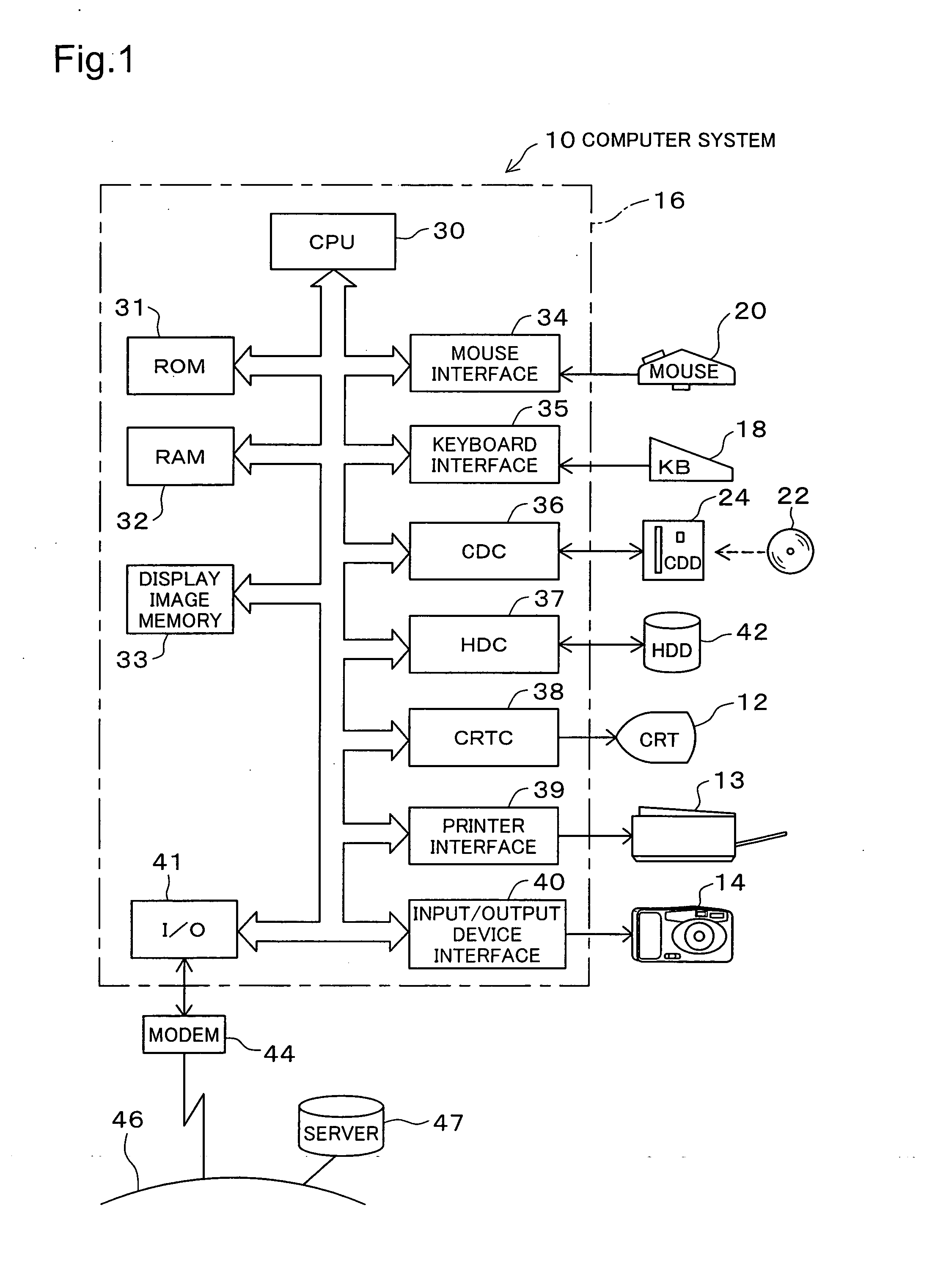
[0118]FIG. 1 is a block diagram schematically illustrating the hardware configuration of a computer system 10 in a first embodiment of the invention. This computer system 10 includes a personal computer (hereafter simply referred to as the computer), as well as a CRT display 12, a printer 13, and a digital camera 14 as peripheral devices. The computer has a computer body 16, a keyboard 18, and a mouse 20. A CD drive (CDD) 24 is mounted on the computer body 16 to read a CD-ROM 22.

[0119] The computer body 16 includes a CPU 30, a ROM 31, a RAM 32, a display image memory 33, a mouse interface 34, a keyboard interface 35, a CD controller (CDC) 36, an hard disk controller (HDC) 37, a CRT controller (CRTC) 38, a printer interface 39, an input / output device interface 40, and an I / O port 41, which are mutually connected via a bus. The ROM 31 stores various programs in a read-only manner, while the RAM 32 stores various data in a readable and wri...

second embodiment

B. Second Embodiment

[0173] A second embodiment of the invention is discussed below.

B-1. System Configuration

[0174] The computer system in the second embodiment of the invention has the same hardware configuration as that of the first embodiment shown in FIG. 1. The like numerals to those of the first embodiment denote the like elements.

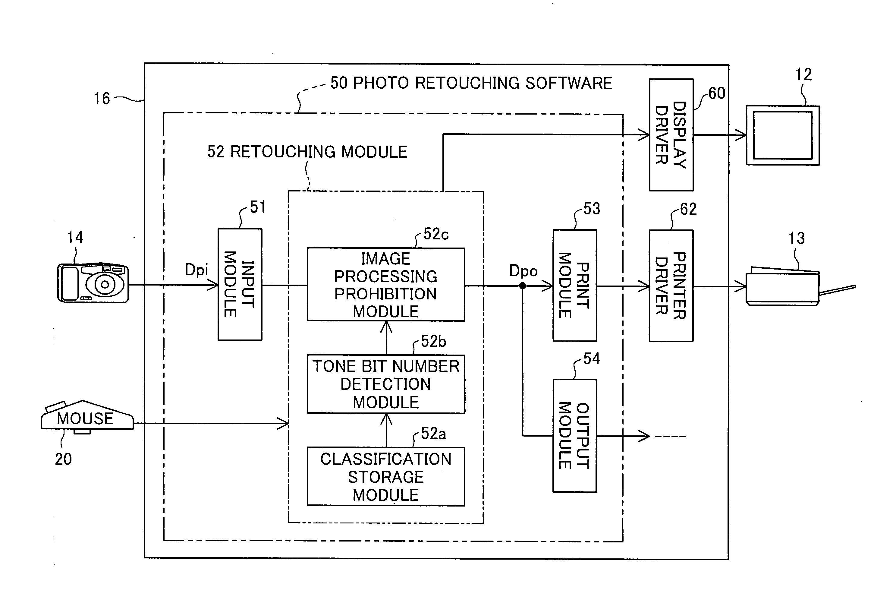
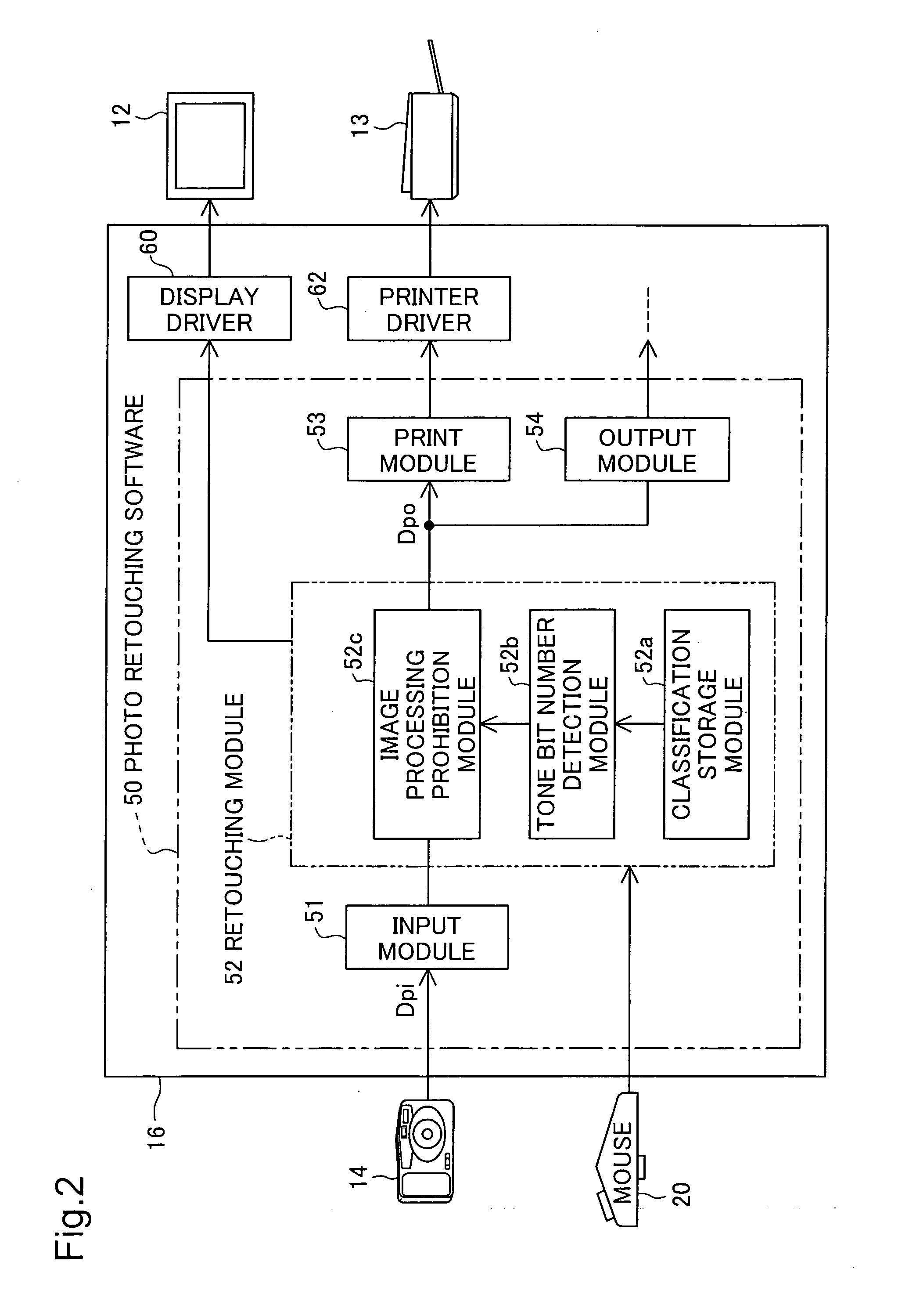
[0175] The software configuration of the second embodiment has some differences from that of the first embodiment. FIG. 10 is a block diagram showing a control flow according to the photo retouching software 50 executed by the computer body 16 in the second embodiment. The only difference from the software configuration of the first embodiment shown in FIG. 2 is the constituents of a retouching module 152.

[0176] The retouching module 152 of the second embodiment has a classification storage module 152a and an execution order control module 152b. The functions of these modules 152a and 152b determine the order of image processing. This is characte...

third embodiment

C. Third Embodiment

[0223] A third embodiment of the invention is discussed below.

C-1. System Configuration

[0224] The computer system in the third embodiment of the invention has the same hardware configuration as that of the first embodiment shown in FIG. 1. The like numerals to those of the first embodiment denote the like elements.

[0225] The software configuration of the third embodiment has some differences from that of the first embodiment. FIG. 22 is a block diagram showing a control flow according to the photo retouching software 50 executed by the computer body 16 in the third embodiment. The only difference from the software configuration of the first embodiment shown in FIG. 2 is the constituents of a retouching module 252.

[0226] The retouching module 252 of the third embodiment includes a layer formation module 252a, an image processing specification module 252b, a tone bit number detection module 252c, a first image processing execution module 252d, a second image pr...


PUM


Abstract

In a computer system of the invention, a menu button BT2 ‘Retouching Pre-Process’ clicked to activate a retouching pre-process and a menu button BT3 ‘Retouching Post-Process’ clicked to activate a retouching post-process are vertically downward aligned in a processing menu window MN corresponding to an order of operation procedure. The retouching pre-process includes 16-bit color support image processing options, for example, ‘brightness adjustment’ and ‘contrast adjustment’. The retouching post-process includes 8-bit color support image processing options, for example, ‘unsharp mask’ and ‘light irradiation’. When the operator clicks the menu button BT2 ‘Retouching Pre-process’ to execute any image processing option included in the retouching pre-process after execution of any image processing option included in the retouching post-process with regard to input image data, the computer system opens a message box to notify the operator of prohibition of a return to the retouching pre-process. The computer system thus effectively prevents execution of any image processing option included in the retouching pre-process after execution of any image processing option included in the retouching post-process. This arrangement desirably prevents potential deterioration of the picture quality in a retouching process that includes both the 16-bit color support image processing and the 8-bit color support image processing.

Description

BACKGROUND OF THE INVENTION [0001] 1. Field of the Invention [0002] The present invention relates to a technique of retouching image data. [0003] 2. Description of the Related Art [0004] Image retouching software executed on the computer is used to readily adjust the brightness and the contrast of image data (see, For example, JP 2000-331180A). This known technique, however, undesirably deteriorates the picture quality of a resulting image by such adjustment. Recently developed retouching software internally handles image data as greater tone bit number data and executes image processing with expression of 16 bits per pixel of image data (48 bits per pixel for RGB) that corresponds to 65536 tones, instead of image processing with expression of 8 bits per pixel of image data (24 bits per pixel for RGB) that corresponds to 256 tones. The 16-bit image processing relieves deterioration of the picture quality. [0005] The image retouching process sequentially executes a series of image pr...

Claims


Application Information

Patent Timeline
Patent Type & Authority Applications(United States)
IPC IPC(8): G06F15/00G06K9/00
CPCH04N1/00931H04N1/40H04N1/00474H04N1/00427H04N1/00413
Inventor HIRAOKA, YASUSHIKOJIMA, TERUHITO
Owner SEIKO EPSON CORP
Why Eureka
Try Eureka