Lens unit and manufacturing method thereof

a technology of lens and manufacturing method, which is applied in the field of lens units, can solve the problems of affecting the workability of assembly, affecting the appearance of the lens, and affecting the quality of the lens, so as to achieve the effect of satisfying assembly workability and being miniaturized

Inactive Publication Date: 2005-10-06
KONICA MINOLTA OPTO
View PDF4 Cites 19 Cited by
  • Summary
  • Abstract
  • Description
  • Claims
  • Application Information

AI Technical Summary

Benefits of technology

[0008] It is a main object of the present invention to provide a lens unit which has s...

Problems solved by technology

The conventional joining method for the lens units, however, has the following problems.
In the joining method using adhesive, it takes a long time to apply and harden adhesive.
Further, an appearance problem due to wrap-around of the adhesive to the lens surface or the like possibly arises.
In the joining method using the ultrasonic welde...

Method used


Image

  • Lens unit and manufacturing method thereof
  • Lens unit and manufacturing method thereof
  • Lens unit and manufacturing method thereof

Examples


first embodiment

[0021] A first embodiment where the present invention is concretized is explained below in detail with reference to the accompanying drawings. In the first embodiment, the present invention is applied to a lens unit where a plurality of optical lenses are combined.

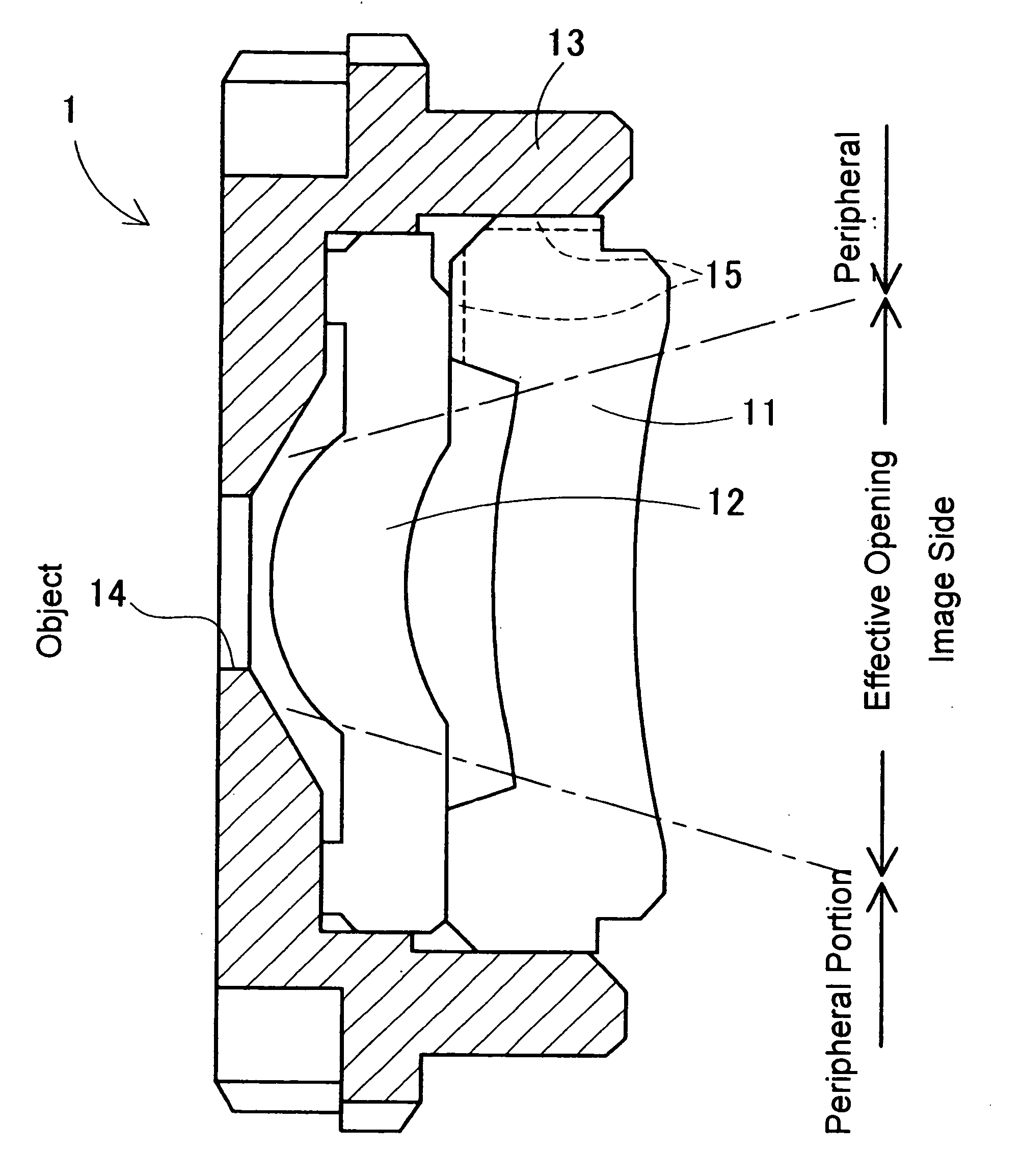
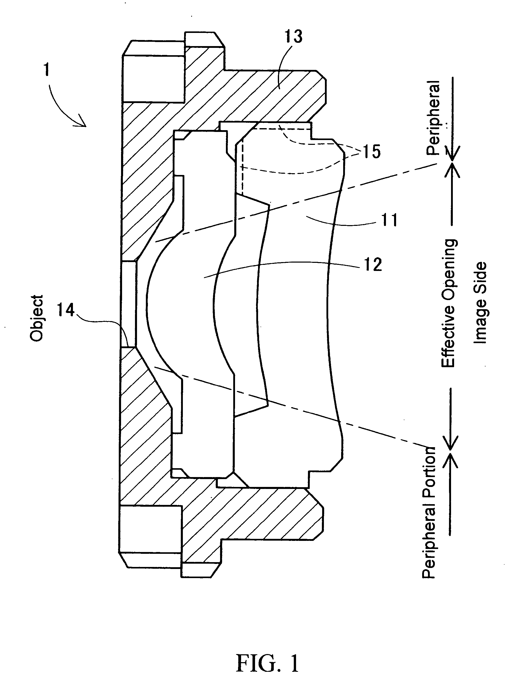
[0022] As shown in FIG. 1, the lens unit 1 of the first embodiment is constituted so that transparent resin lenses 11 and 12 are combined so as to be installed in a lens barrel 13. In the drawing, a left side is an object side, and an imaging surface is arranged on a right side. The lens barrel 13 is provided with a through hole 14 on a center portion of the object side. Light which passes from the object side through the through hole 14 reaches the imaging surface via the resin lenses 11 and 12.

[0023] The resin lens 11 is a general transparent lens. The resin lens 11 transmits light well in both visible area and infrared area. The resin lens 12 contains infrared absorbent which is publicly known as transparent resin (fo...

second embodiment

[0035] A second embodiment where the present invention is concretized is explained in detail below with reference to the accompanying drawings. The second embodiment is a lens unit which is used in cameras or the like having solid-state image sensing devices such as CCD, and the present invention is applied to the lens unit having three or more optical lenses.

[0036] The lens unit 2 of the second embodiment is, as shown in FIG. 4, constituted so that three transparent resin lenses 21, 22 and 23 are combined. In FIG. 4, a left side in the drawing is the object side, and an image pickup device such as CCD is arranged on a right side. Light which transmits from the object side through the resin lenses 21, 22 and 23 is imaged on an imaging surface of the image pickup device.

[0037] In the lens unit 2 of the second embodiment, the infrared absorbent is contained in the effective opening of any one of the resin lenses 21, 22 and 23. As a result, an infrared portion of the light which ente...

third embodiment

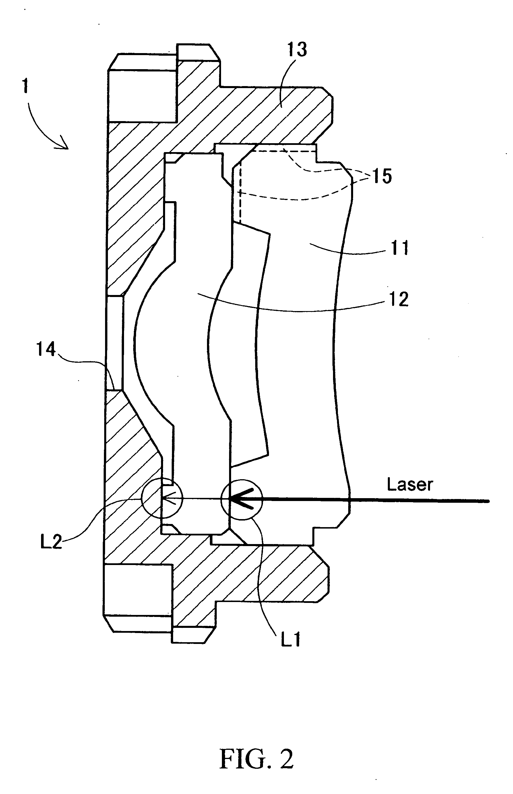
[0042] The infrared absorbent is used in the first and the second embodiments. On the contrary, in a third embodiment, instead of the infrared absorbent, ultraviolet absorbent is contained in the transparent resin lens, and ultraviolet laser is emitted so that the resin lenses are welded.

[0043] The lens unit 3 of the third embodiment has the same shape as that of the lens unit 1 in the first embodiment as shown in FIG. 5. The resin lens 31 is formed by a material which transmits visible light and ultraviolet ray well, and the resin lens 32 is formed so that the transparent resin contains the ultraviolet absorbent. As the ultraviolet absorbent, publicly-known materials (for example, compounds such as benzophenone, benzotriazole, phenyl salicate and cyanoacrylate) can be used. The lens barrel 33 is formed by a material which absorbs the light in both the visible area and the ultraviolet area.

[0044] As shown in FIG. 6, the transmittance of the resin lens 32 for each wavelength varies...


PUM

PropertyMeasurementUnit
Timeaaaaaaaaaa
Volumeaaaaaaaaaa
Transparencyaaaaaaaaaa

Abstract

In the case where a lens unit where two ore more transparent resin lenses are combined is constituted, at least one transparent resin lens contains infrared absorbent. When the lens unit is assembled, an infrared laser is emitted to a joined portion between the transparent resin lens and the other transparent resin lens. As a result, the emitted infrared ray is absorbed by the infrared absorbent, so that the transparent resin lenses are welded to each other. An opaque lens barrel which holds the entire lens unit and the transparent resin lenses are joined by welding.

Description

[0001] The present application claims priority to Japanese Patent Application No. 2004-106849 filed in Mar. 31, 2004 and No. 2004-192785 filed Jun. 30, 2004, the entire contents of which are hereby incorporated by reference. BACKGROUND OF THE INVENTION [0002] 1. Field of the Invention [0003] The present invention relates to a lens unit including a plurality of transparent resin lenses and a manufacturing method thereof. More concretely, the invention relates to the lens unit where a plurality of resin lenses are held in a lens barrel which covers them, and the manufacturing method thereof. [0004] 2. Description of the Related Art [0005] Conventionally, a lot of transparent lenses made of resin are used as optical lenses. Particularly a plurality of resin lenses are mostly combined to be used as lenses for cameras. For this reason, the resin lenses or the resin lenses and a lens barrel for holding them should be fixed to one another. In such resin lenses, an area for joining is forme...

Claims


Application Information

Patent Timeline
IPC IPC(8): B29C65/00B29C65/14B29C65/16B29D11/00G02B7/02G02B9/04G02B27/10
CPCB29C65/1406Y10S359/90B29C65/1606B29C65/1612B29C65/1635B29C65/1677B29D11/00009B29L2011/0016G02B7/021B29C65/1403B29C65/1435B29C65/1477B29C65/1603B29C65/1654B29C66/21B29C66/543B29C66/545B29C65/1412
Inventor UEHIRA, MASAYOSHIMATSUMOTO, AKIHIKOWATANABE, KATSUSHIMAJIMA, TOSHIYUKI
Owner KONICA MINOLTA OPTO
Why Eureka
Try Eureka