

Device and method for erasing recorded data of magnetic storage
a magnetic storage and eraser technology, applied in the field of erasers, can solve the problems of unidirectional drive magnetization, heavy workload and time-consuming, and inability to effectively erase recorded data
- Summary
- Abstract
- Description
- Claims
- Application Information
AI Technical Summary
Benefits of technology
Problems solved by technology
Method used
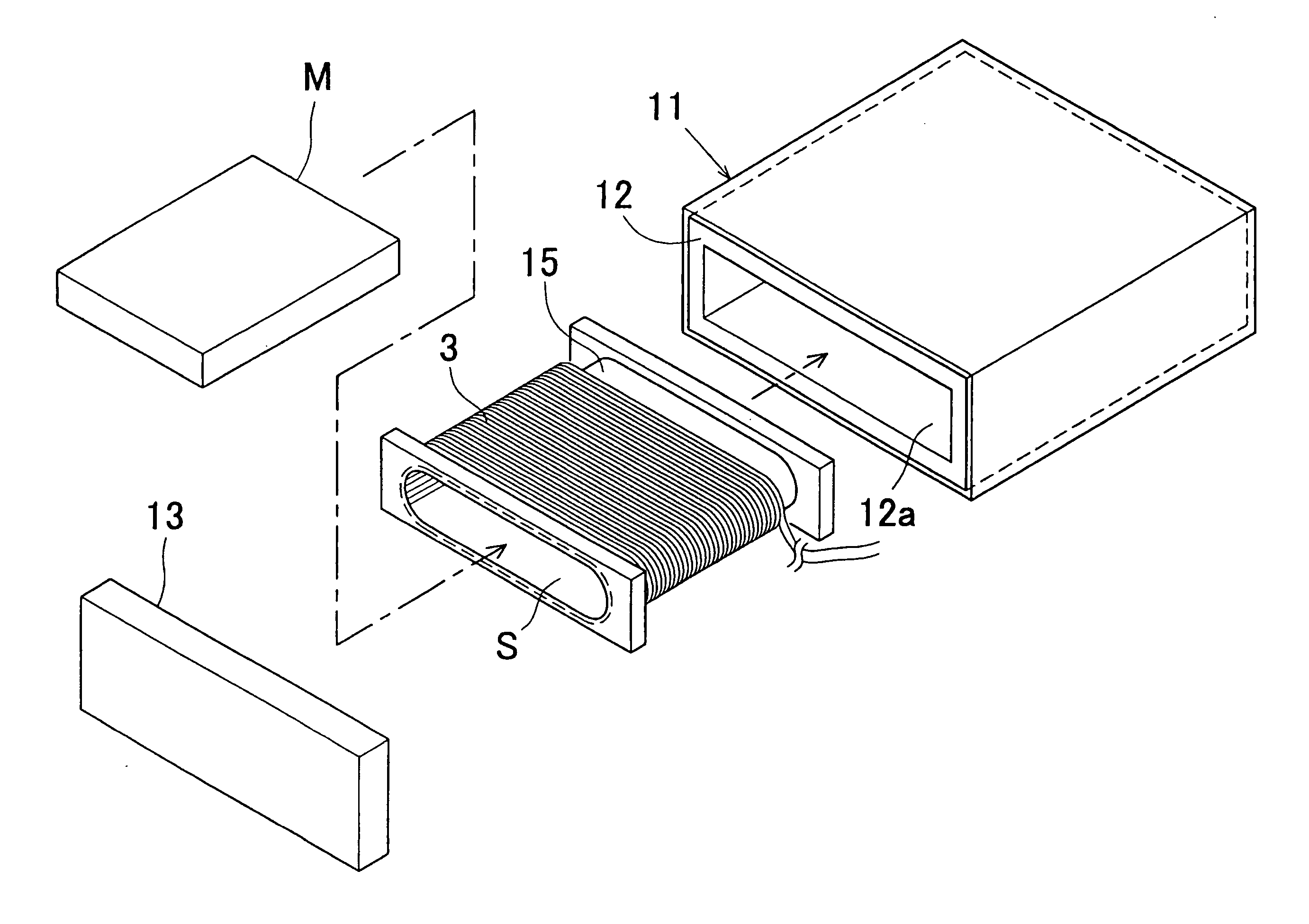
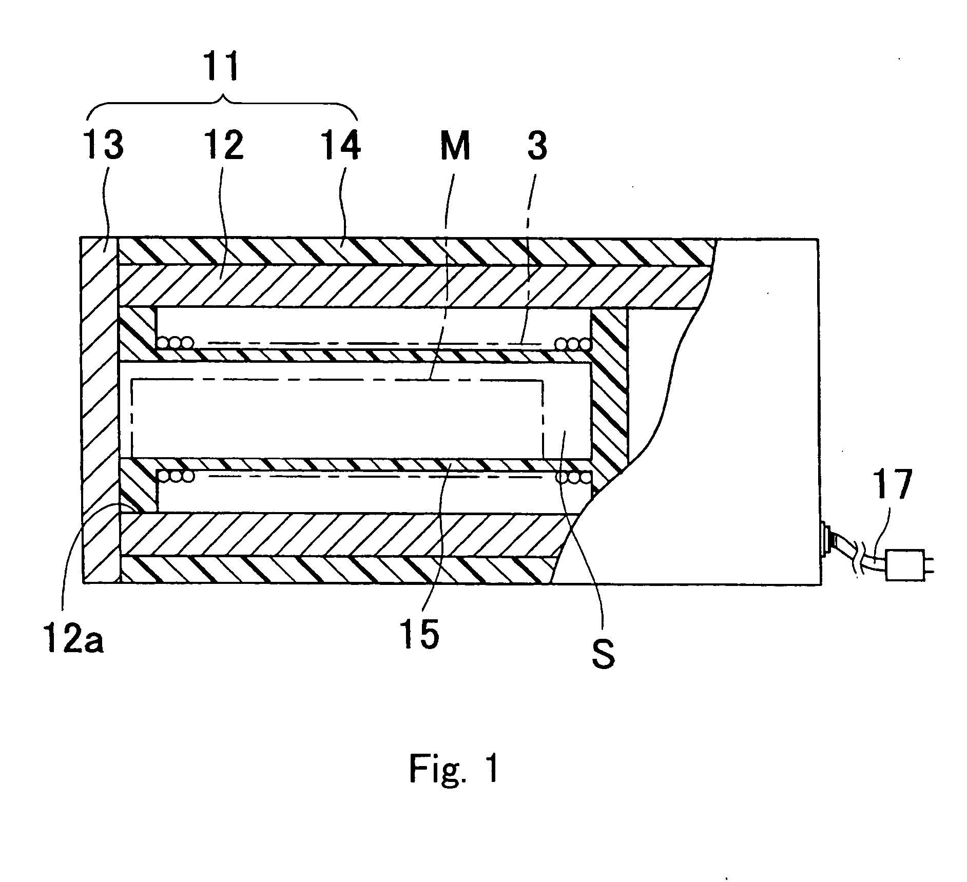
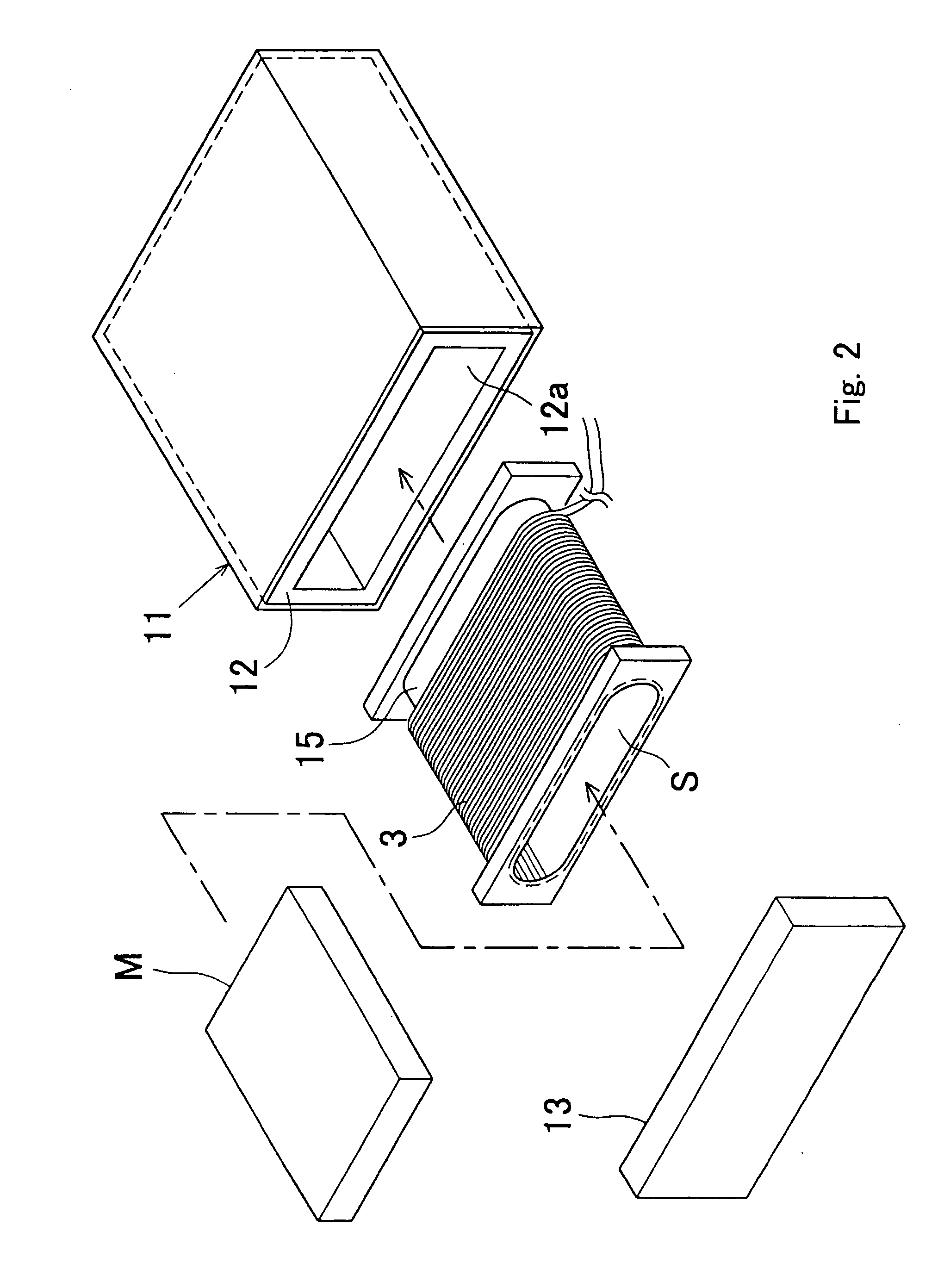
Image

Examples
first embodiment
[0052] [First Embodiment]
[0053] An eraser of the first embodiment was set with a diameter of the coil 3 of 1.2 mm or more, its internal resistance of 2.5 ohm, the inductance of the coil 3 of 100H, the voltage applied to the capacitor 5 of 380V, and the capacity of the capacitor 5 of 4,700 microfarad.
[0054] In measuring the transient voltage and time characteristic of the discharge under this condition, as seen in FIG. 4, substantially four times of the rebound phenomena were generated by a discharge. In this case, recorded data on the hard disk in the hard disk drive was completely erased.
second embodiment
[0055] [Second Embodiment]
[0056] An eraser of the second embodiment was set with the diameter of the coil 3 of 1.2 mm or more, its internal resistance of 5 ohm, the inductance of the coil 3 of 200H, the voltage applied to the capacitor 5 of 380V, and the capacity of the capacitor 5 of 4,700 microfarad.
[0057] In measuring the transient voltage and time characteristic of the discharge under this condition, as seen in FIG. 5, substantially three times of the rebound phenomena were generated by a discharge. In this case, recorded data on the disk in the drive was also completely erased.
third embodiment
[0058] [Third Embodiment]
[0059] An eraser of the third embodiment was set with the diameter of the coil 3 of 1.2 mm or more, its internal resistance of 5 ohm, the inductance of the coil 3 of 100H, the voltage applied to the capacitor 5 of 1,000V, and the capacity of the capacitor 5 of 9,400 microfarad.
[0060] In measuring the transient voltage and time characteristic of the discharge under this condition, as seen in FIG. 6, substantially a little less than twice of the rebound phenomena were generated by a discharge. In this case, recorded data on the disk in the drive was also erased with a high accuracy.
PUM
| Property | Measurement | Unit |
|---|---|---|
| internal resistance | aaaaa | aaaaa |
| diameter | aaaaa | aaaaa |
| voltage | aaaaa | aaaaa |
Abstract
Description
Claims
Application Information