Automatic vehicle exterior light control

a technology of automatic control and vehicle exterior, which is applied in the direction of point-like light sources, lighting and heating apparatus, transportation and packaging, etc., can solve the problems of inability to consider oncoming or leading vehicles in determining the illumination range of headlamps, the increase in the brightness and bluish color of hid lamps is particularly disruptive to oncoming drivers, and the change in illumination that may startle drivers

Inactive Publication Date: 2005-10-06
STAM JOSEPH S +2
View PDF11 Cites 213 Cited by
  • Summary
  • Abstract
  • Description
  • Claims
  • Application Information

AI Technical Summary

Benefits of technology

[0016] The present invention may control continuously variable headlamps based on detected headlamps from oncoming vehicles and tail lights from leading vehicles. The control system may determine the proper aim of headlamps in steerable headlamp systems and may determine the proper intensity of headlamps in variable intensity headlamp systems. Gradual changes in the region of headlamp illumination may be supported. The control system also operates correctly over a wide range of ambient lighting conditions.

Problems solved by technology

Also, continuously varying the headlamp illumination does not create rapid changes in illumination that may startle the driver.
The increased brightness and bluish color of the HID lamps is particularly disrupting to oncoming drivers.
Due to this disruptness effect, certain European countries require headlamp leveling systems if HID lamps are used on a vehicle.
One problem with current continuously variable headlamp control systems is the inability to consider oncoming or leading vehicles in determining the illumination range of headlamps.
This design presents many problems.
Second, placing the image sensor on the lower front portion of the vehicle may result in imaging surfaces being coated with dirt and debris.
Third, placing the image sensor close to the headlamp beam makes the system subject to the masking effects of scattered light from fog, snow, rain, or dust particles in the air.
Fourth, this system has no color discriminating capability and, with only five pixels of resolution, the imaging system is incapable of accurately determining lateral and elevational locations of headlamps or tail lights at any distance.

Method used


Image

  • Automatic vehicle exterior light control
  • Automatic vehicle exterior light control
  • Automatic vehicle exterior light control

Examples


Embodiment Construction

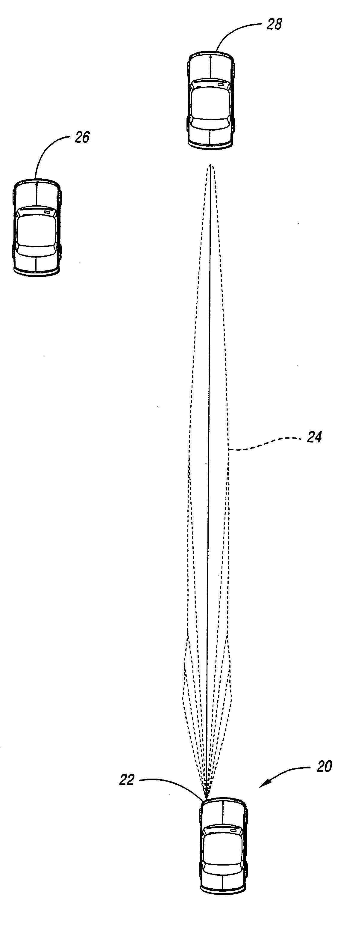
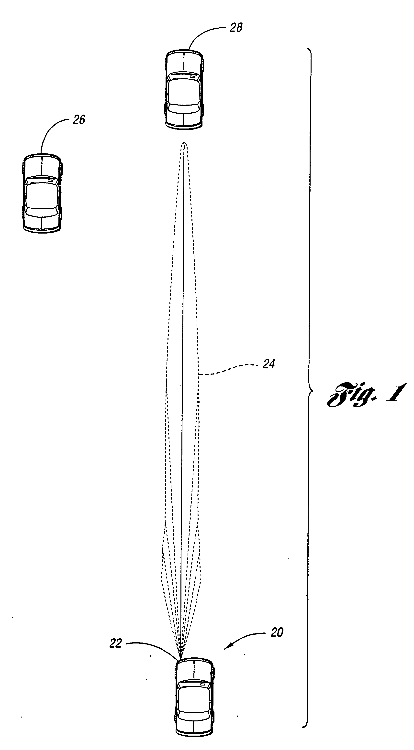
[0060] Referring now to FIG. 1, a continuously variable headlamp illumination range together with oncoming and leading vehicles is shown. Controlled vehicle 20 includes at least one continuously variable headlamp 22. Each headlamp 22 produces a variable region of bright light known as illumination range 24. A driver in oncoming vehicle 26 or leading vehicle 28 that is within illumination range 24 may view headlamps as producing excessive glare. This glare may make it difficult for the driver of oncoming vehicle 26 or leading vehicle 28 to see objects on the road, to read vehicle instruments, and to readjust to night viewing conditions once vehicle 26, 28 is outside of illumination range 24. Hence, illumination range 24 is perceived as a glare area by the driver of oncoming vehicle 26 or leading vehicle 28.

[0061] The present invention attempts to reduce the level of glare seen by the driver of oncoming vehicle 26 or leading vehicle 28 by providing a control system that detects oncom...


PUM


Abstract

A system for automatically controlling continuously variable headlamps on a controlled vehicle includes an imaging system capable of determining lateral and elevational locations of headlamps from oncoming vehicles and tail lamps from leading vehicles. The system also includes a control unit that can acquire an image from in front of the controlled vehicle. The image covers a glare area including points at which drivers of oncoming and leading vehicles would perceive the headlamps to cause excessive glare. The image is processed to determine if at least one oncoming or leading vehicle is within the glare area. If at least one vehicle is within the glare area, the headlamp illumination range is reduced. Otherwise, the illumination range is set to full illumination range.

Description

CROSS-REFERENCE TO RELATED APPLICATIONS [0001] This application is a continuation of U.S. patent application Ser. No. 10 / 617,323, entitled “CONTINUOUSLY VARIABLE HEADLAMP CONTROL,” filed on Jul. 10, 2003, by Joseph S. Stam et al., which is a continuation of U.S. patent application Ser. No. 10 / 197,834, entitled “CONTINUOUSLY VARIABLE HEADLAMP CONTROL,” filed on Jul. 18, 2002, by Joseph S. Stam et al., now U.S. Pat. No. 6,593,698, which is a continuation of U.S. patent application Ser. No. 09 / 938,774, entitled “CONTINUOUSLY VARIABLE HEADLAMP CONTROL,” filed on Aug. 24, 2001, by Joseph S. Stam et al., now U.S. Pat. No. 6,429,594, which is a continuation of U.S. patent application Ser. No. 09 / 546,858, entitled “CONTINUOUSLY VARIABLE HEADLAMP CONTROL,” filed on Apr. 10, 2000, by Joseph S. Stam et al., now U.S. Pat. No. 6,281,632, which is a continuation of U.S. patent application Ser. No. 09 / 157,063, entitled “CONTINUOUSLY VARIABLE HEADLAMP CONTROL,” filed on Sep. 18, 1998, by Joseph S. ...

Claims


Application Information

Patent Timeline
Patent Type & Authority Applications(United States)
IPC IPC(8): B60Q1/08B60Q1/02B60Q1/12B60Q1/14B60Q1/18F21V1/00
CPCB60Q1/085B60Q1/1423B60Q1/18B60Q2300/054B60Q2300/056B60Q2300/112B60Q2400/30B60Q2300/132B60Q2300/312B60Q2300/314B60Q2300/3321B60Q2300/41B60Q2300/42B60Q2300/114G06V20/584B60Q1/14
Inventor STAM, JOSEPH S.BECHTEL, JON H.BAUER, FREDERICK T.
Owner STAM JOSEPH S
Why Eureka
Try Eureka