Control circuit for switching power supply
- Summary
- Abstract
- Description
- Claims
- Application Information
AI Technical Summary
Benefits of technology
Problems solved by technology
Method used
Image
Examples
Embodiment Construction
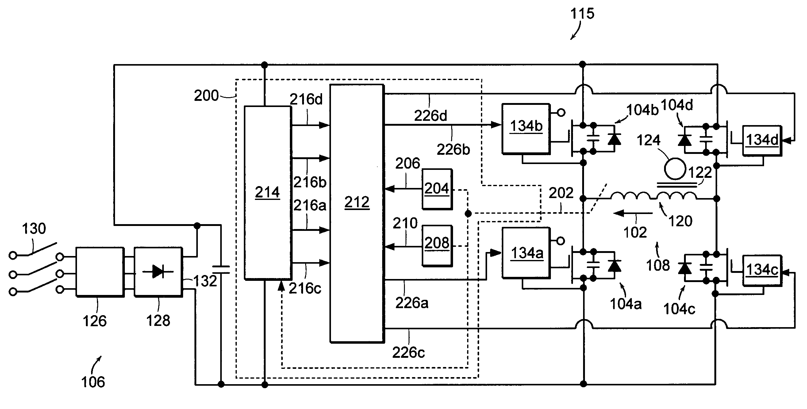
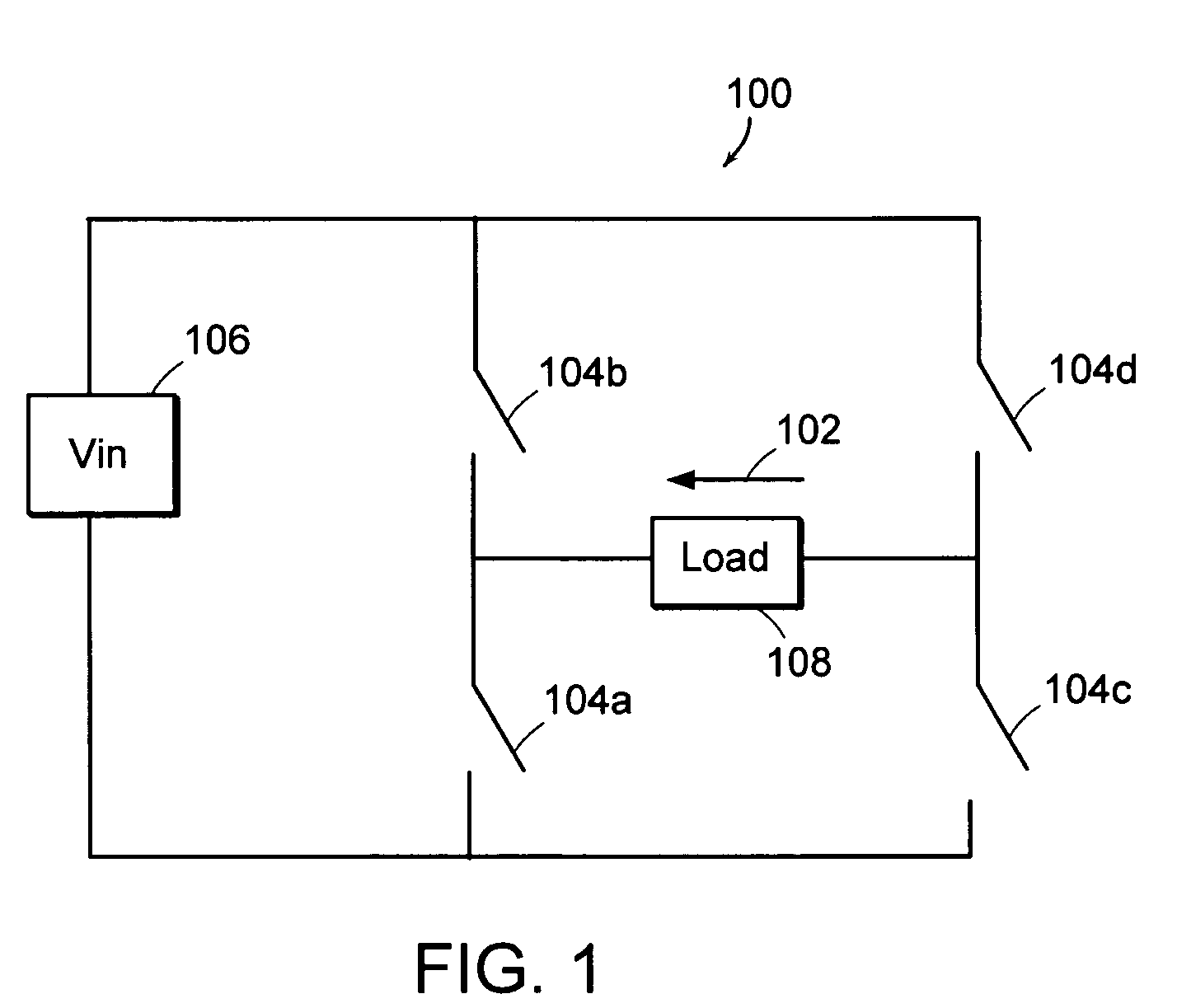
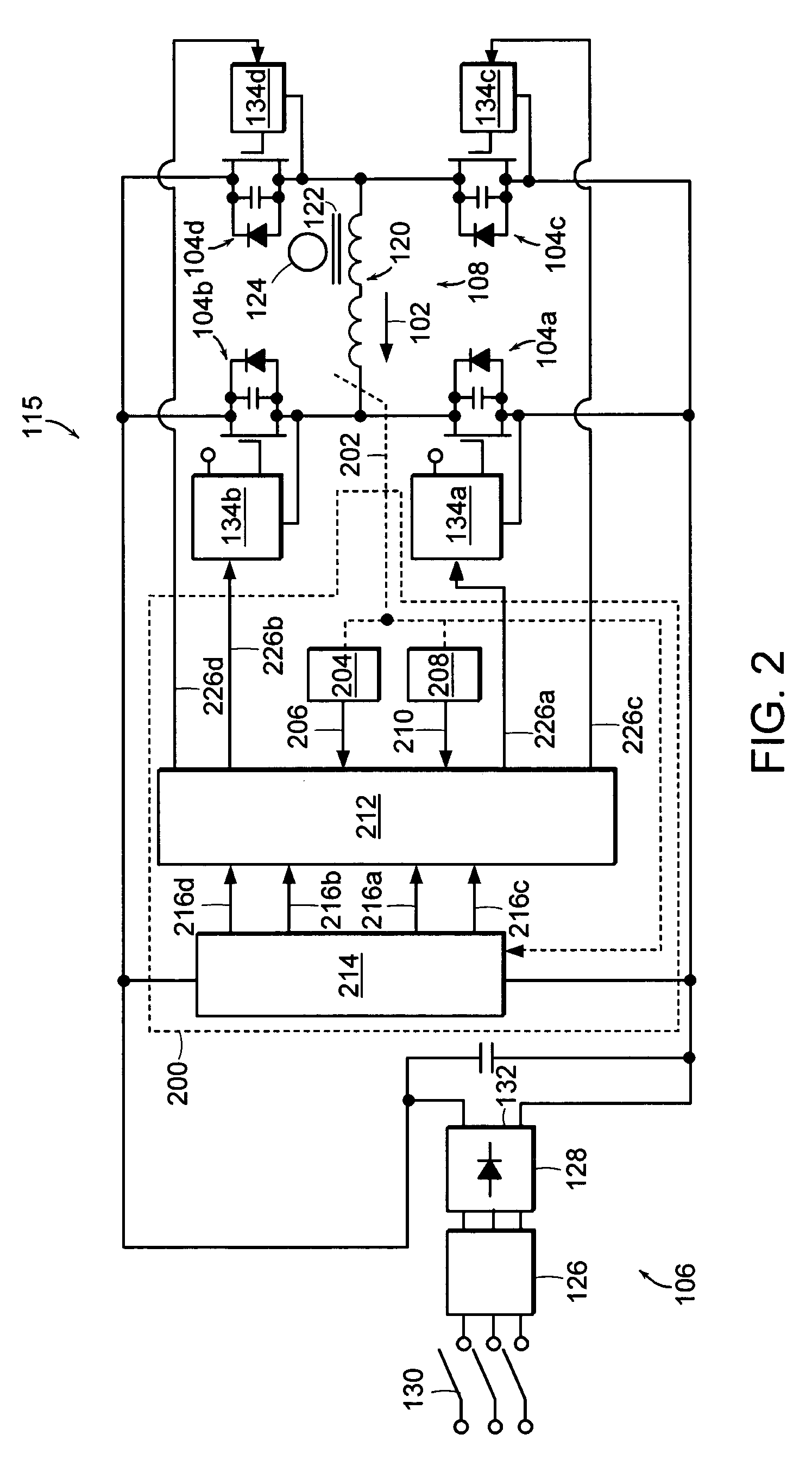
[0026]FIG. 1 depicts an exemplary switching power supply. More particularly, FIG. 1 depicts a full bridge converter circuit 100. As described herein, the full bridge converter circuit 100 is a phase modulated full bridge converter circuit 100, a common choice for high frequency applications. The phase modulated full bridge converter circuit 100 is an exemplary switching power supply for which a load current 102 can be controlled and, in the case of an over current condition, can be quickly corrected by the control circuit 200 (see FIG. 2) according to the invention. It should be noted, however, that the control circuit 200 could, with appropriate modifications, also be used to control and / or correct the load current of other converter circuits, such as, for example, a push-pull converter, a half-bridge converter, or a pulse width modulated full-bridge converter.
[0027] As illustrated in FIG. 1, the full bridge converter circuit 100 includes first, second, third, and fourth switches ...
PUM
 Abstract
Description
Claims
Application Information
 - R&D
- Intellectual Property
- Life Sciences
- Materials
- Tech Scout
- Unparalleled Data Quality
- Higher Quality Content
- 60% Fewer Hallucinations
Browse by: Latest US Patents, China's latest patents, Technical Efficacy Thesaurus, Application Domain, Technology Topic, Popular Technical Reports.
© 2025 PatSnap. All rights reserved.Legal|Privacy policy|Modern Slavery Act Transparency Statement|Sitemap|About US| Contact US: help@patsnap.com


