Echo cancellation

Active Publication Date: 2005-10-06
GOOGLE LLC
View PDF6 Cites 20 Cited by
  • Summary
  • Abstract
  • Description
  • Claims
  • Application Information

AI Technical Summary

Benefits of technology

[0020] According to an embodiment of the invention, the echo cancellation is based on two or more linear filters, each filter generating a replica of a corresponding reflection energy concentration included in an echo based on a corresponding delayed input signal from a buffer. Thus, the different filters of the echo canceller are adapted to the different delays of different energy concentrations of a reflection. In this way the invention enables an even more improved cancellation of echoes that include two or more separated energy concentrations.
[0021] According to another embodiment, the basis for increasing the replica delay provided by the buffer is a relationship between the energy, measured as sum-squares of filter coefficients, of the beginning of the filter associated with short delays and the energy of the full length filter, i.e. the estimated echo return loss. If the energy measured in the beginning of the filter is low, the delay is increased. Correspondingly, if the energy measured for the coefficients of the tailing part of the filter is low in comparison with the energy of the f

Problems solved by technology

An echo, which is a delayed version of what was originally transmitted, is regarded as a severe distraction to the speaker if the delay is long.
For short round trip delays of less than approximately 20 ms, the speaker will not be able to distinguish the echo from the side tone in the handset.
However, for long-distance communications, such as satellite communications, a remotely generated echo signal often has a substantial delay.
Moreover, the speech and channel coding compulsory in digital radio communications systems and for telephony over the Internet protocol (IP telephony, for short) also result in significant delays which makes the echoes generated a relatively short distance away clearly audible to the

Method used


Image

  • Echo cancellation
  • Echo cancellation
  • Echo cancellation

Examples


Example

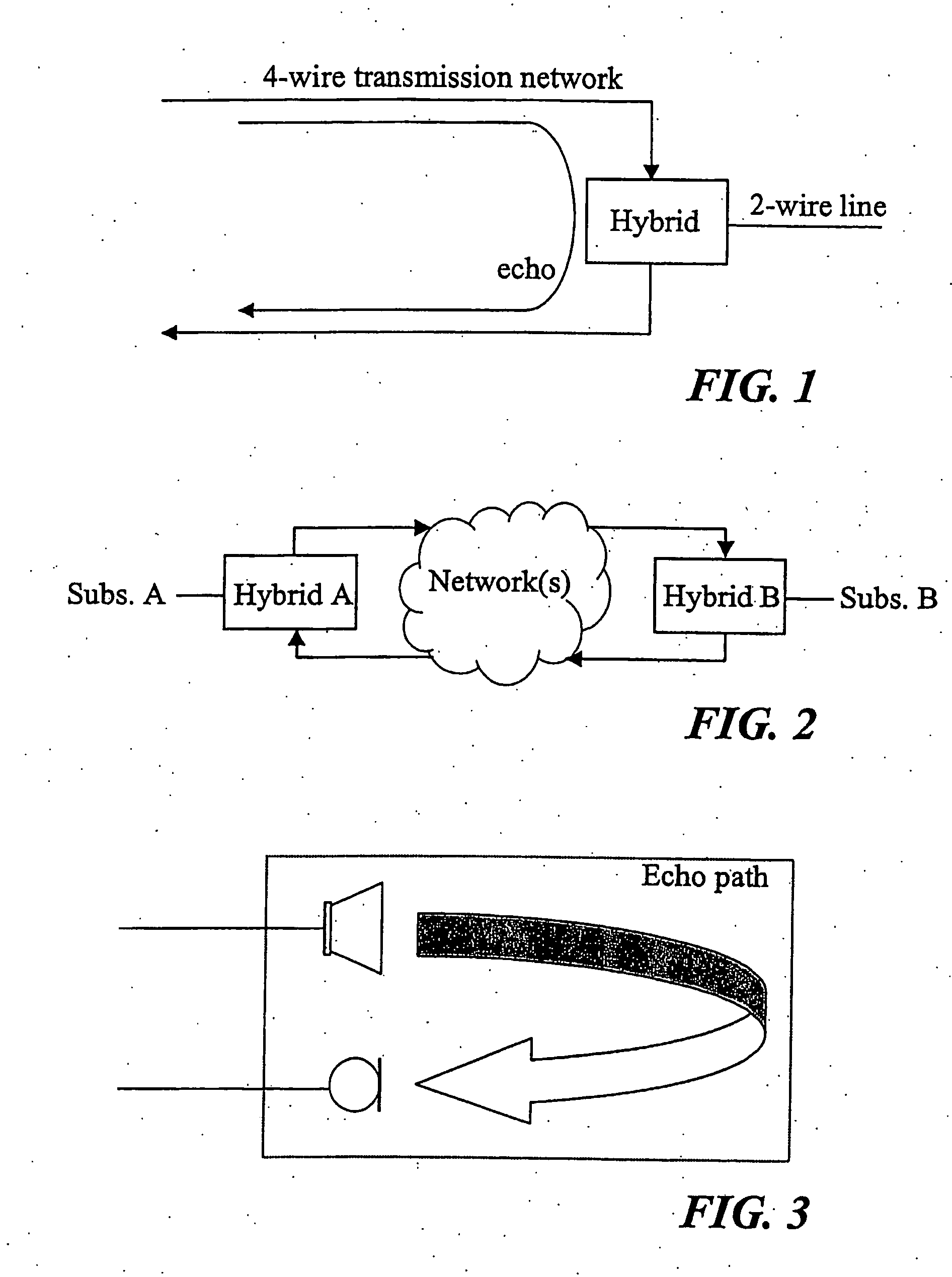
[0032]FIGS. 1-3 exemplify different types of echoes which advantageously are cancelled by the present invention.

[0033]FIGS. 1 and 2 illustrates the occurrence of network echo. FIG. 1 shows the echo originating from a hybrid to which a subscriber by means of a 2-wire line is connected, i.e. the echo from the Public Switched Telephone Network (PSTN) line interface to which the subscriber is connected. FIG. 2 shows two PSTN phones interconnected via one or more networks, such as via satellite transmission paths, an IP network or a radio network. The signal from subscriber A is partly reflected at Hybrid B and returned to subscriber A as a network echo. Subscriber A would also receive a network echo if he were to be directly connected to a IP network or a radio network, such as a digital cellular communications network.

[0034]FIG. 3 shows the occurrence of acoustic echo due to cross talk between a loudspeaker and a microphone of a handset or a hands free equipment.

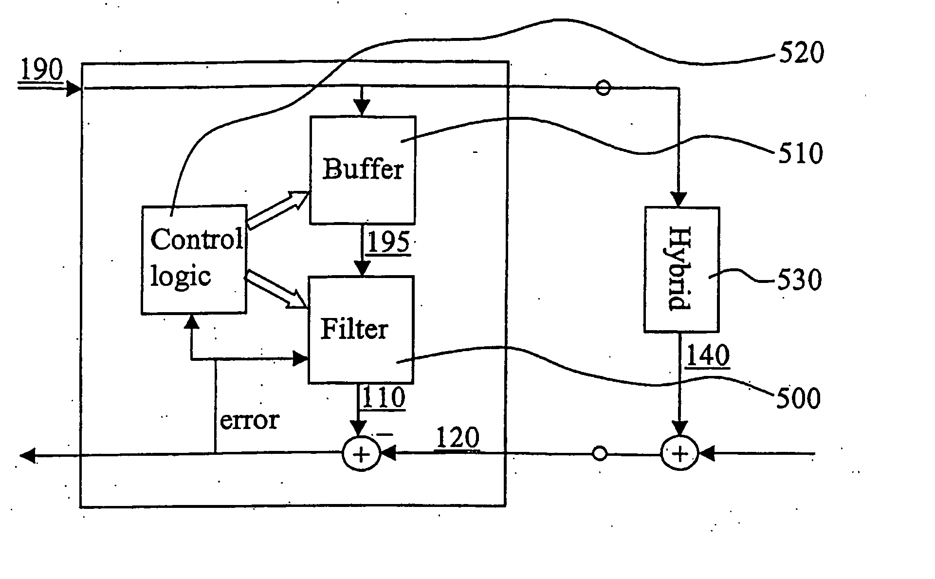
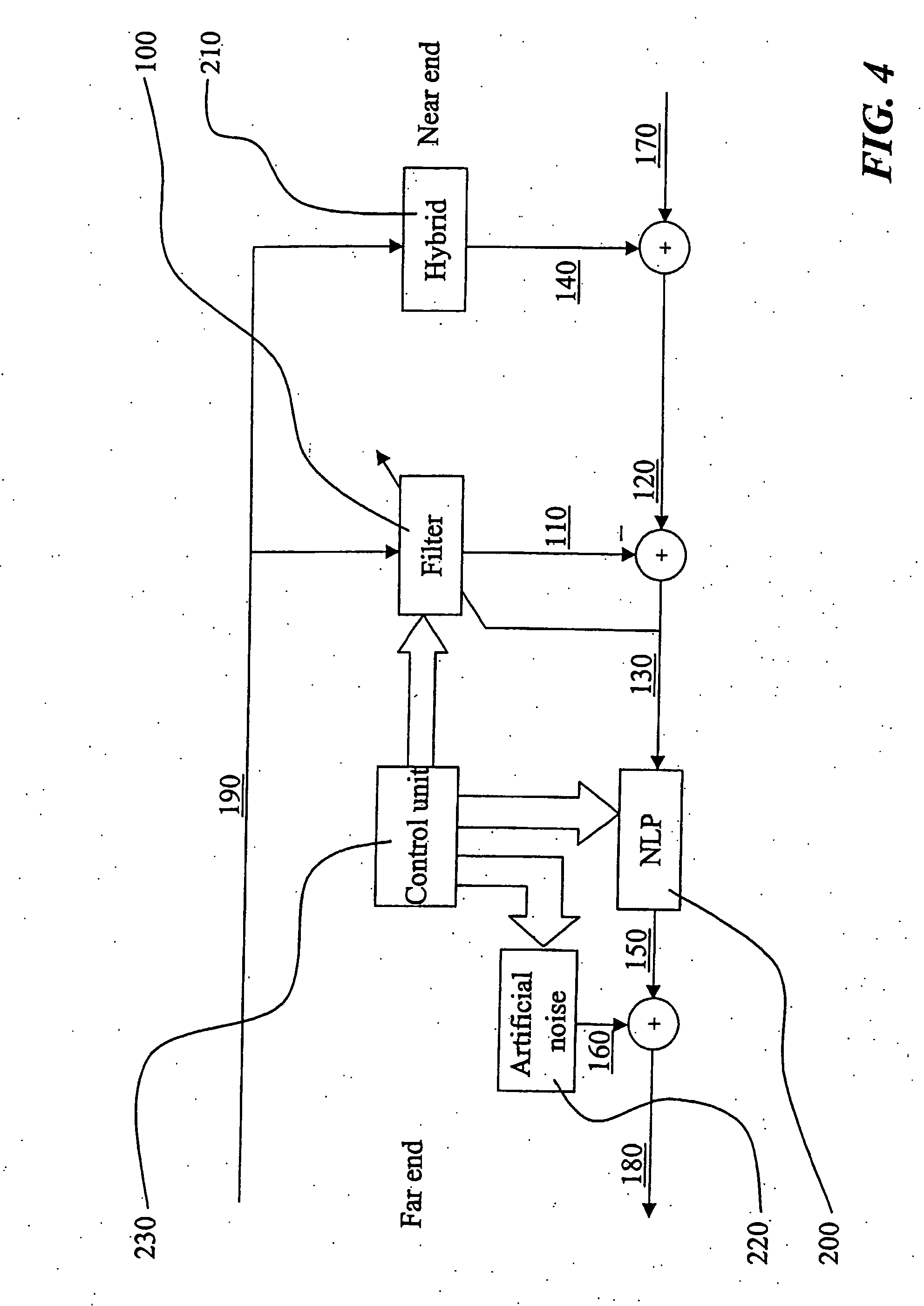
[0035]FIG. 4 shows a...


PUM


Abstract

The present invention relates to a cancellation of echoes in telecommunications systems, more specifically it relates to adaptive alignment of a linear filter (500) used for echo cancellation. According to the invention, it is continuously determined, by means of control logic (520), if a reflection replica delay included in an echo replica signal (110), which delay is provided by a signal buffer (510), should be attempted to be increased or not. Similarly, it is continuously determined if the reflection replica delay should be attempted to be decreased or not. In this way it is possible to provide a delay of the reflection replica which corresponds to the pure delay of a corresponding reflection included in an echo signal (120) received over an echo path. The invention is advantageous since the filter (500) will continuously and quickly adapt to changes in the echo path delay by continuously increasing or decreasing, in an incremental and smooth manner, a present replica delay.

Description

TECHNICAL FIELD OF THE INVENTION [0001] The present invention generally relates to cancellation of echoes in telecommunications systems, more specifically it relates to adaptive alignment of linear filters used for echo cancellation. TECHNICAL BACKGROUND AND PRIOR ART [0002] Speech quality is an important factor for telephony system suppliers. The demand from the customers makes it vital to strive for continuous improvements of the systems. An echo, which is a delayed version of what was originally transmitted, is regarded as a severe distraction to the speaker if the delay is long. For short round trip delays of less than approximately 20 ms, the speaker will not be able to distinguish the echo from the side tone in the handset. However, for long-distance communications, such as satellite communications, a remotely generated echo signal often has a substantial delay. Moreover, the speech and channel coding compulsory in digital radio communications systems and for telephony over th...

Claims


Application Information

Patent Timeline
IPC IPC(8): H04B3/23
CPCH04B3/23
Inventor HANDEL, PETERBERGENHEIM, JONREMLE, SUSANNE
Owner GOOGLE LLC
Why Eureka
Try Eureka