Method of transmitting data from a transmitter to a receiver, and a radio system

a radio system and receiver technology, applied in the direction of transmission monitoring, electromagnetic wave modulation, polarisation/directional diversity, etc., can solve the problems of deteriorating the performance of the receiver and thus the capacity of the system, significant delays in decoding, and channel coding is not sufficient on its own on fading channels, so as to improve the cancellation of interference, improve the transmission capacity of the radio system, and reduce the effect of interferen

Inactive Publication Date: 2007-10-23
NOKIA CORP
View PDF20 Cites 4 Cited by
  • Summary
  • Abstract
  • Description
  • Claims
  • Application Information

AI Technical Summary

Benefits of technology

[0016]The invention is based on the idea of replacing the interleaving with the use of transmitter diversity antennas, whereby decoding of the channel-coding can be performed prior to the estimation and cancellation of the multiple access interference in the receiver. The decoded data can then be utilized to attenuate the interference in the receiver. This improves the cancellation of the interference. Hereby, the radio system can have more users at the same time, in other words the transmission capacity of the radio system can be increased with the method according to the invention.

Problems solved by technology

In addition, in CDMA (Code Division Multiple Access) radio systems, multiple access interference, MAI, which is caused by the non-orthogonality of the users' spreading codes, deteriorates the performance of the receiver and thus the capacity of the system.
Channel coding is not sufficient on its own on fading channels, because the coherence time of the channel is usually much longer than the duration of a symbol.
This is alleviated by interleaving, but it causes significant delays in decoding, particularly in environments where the subscriber terminal moves slowly, for instance indoors.
The problem of the delays in the decoding makes the designing of receivers operating at a high transmission speed particularly indoors more difficult.
This causes two problems: a long decision delay and large memory buffers to collect the interleaved data.

Method used


Image

  • Method of transmitting data from a transmitter to a receiver, and a radio system
  • Method of transmitting data from a transmitter to a receiver, and a radio system
  • Method of transmitting data from a transmitter to a receiver, and a radio system

Examples


Embodiment Construction

[0023]The examples describe the use of the invention in a universal mobile telecommunications system, UMTS, using a wideband code division multiple access method, without limiting the invention to this, however. The presented solution can also be applied to TDMA (Time Division Multiple Access) systems, such as the GSM (Global System For Mobile Communication) system.

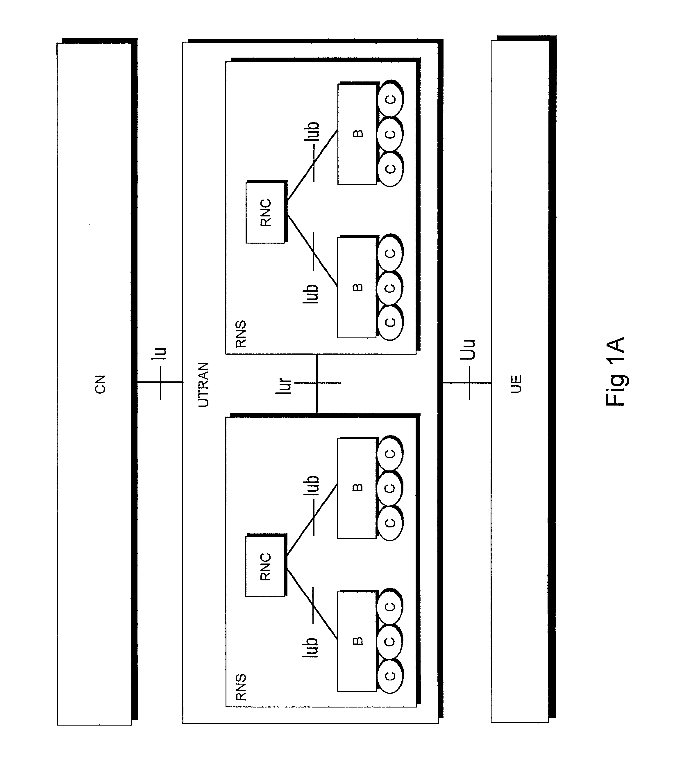
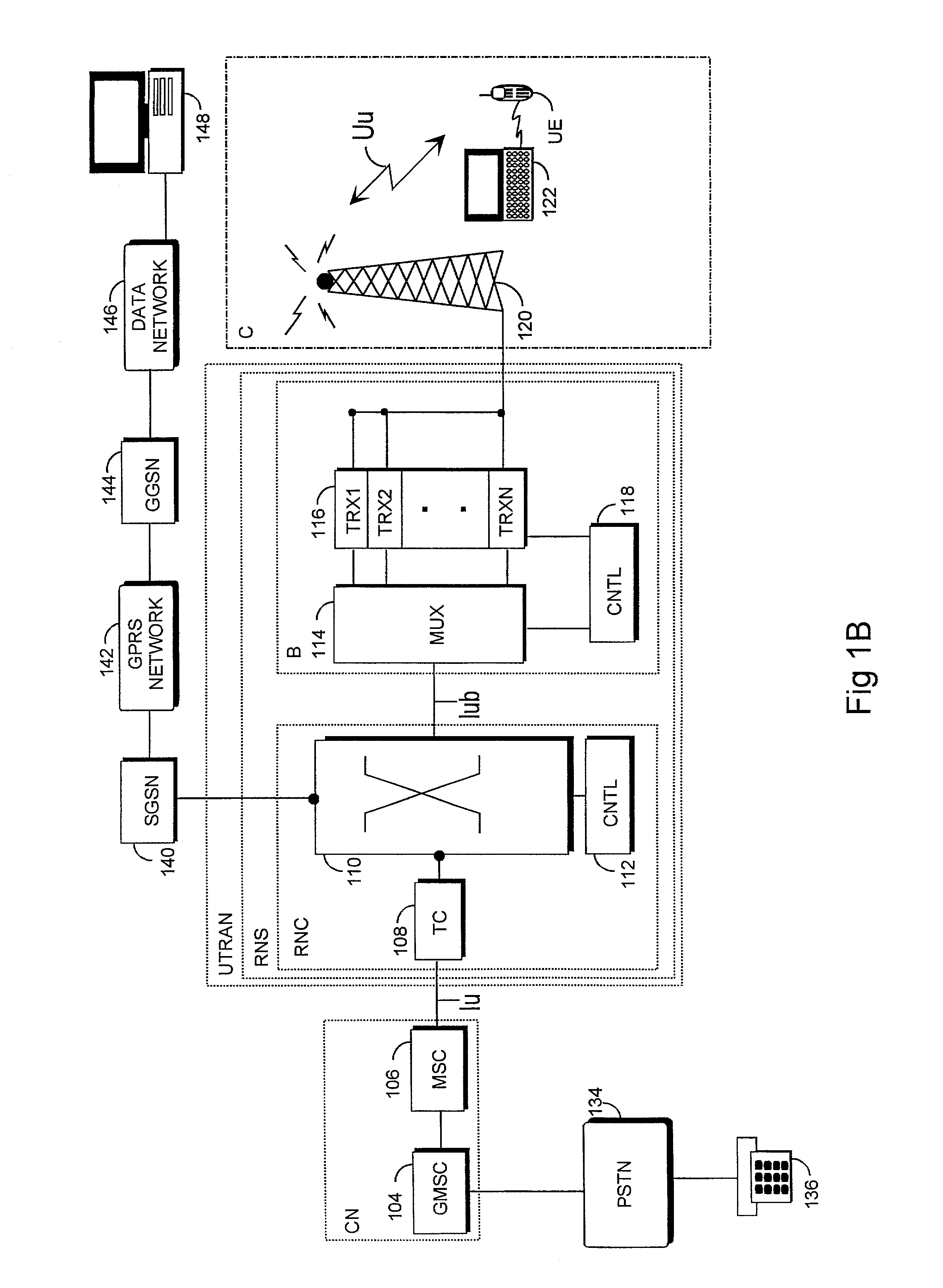
[0024]With reference to FIGS. 1A and 1B, the structure of a universal telecommunications system is described. FIG. 1B only contains the blocks essential for the clarification of the invention, but it is obvious to a person skilled in the art that a conventional mobile communications system also contains other functions and structures, the detailed explanation of which is not necessary herein. The main parts of the mobile communications system are a core network CN, a UMTS terrestrial radio access network UTRAN, and user equipment UE. The interface between the CN and the UTRA is called lu, and the air interface between the...


PUM


Abstract

The invention relates to a method of transmitting data from a transmitter to a receiver in a radio system, and to a radio system. The method includes the following: channel-coding the data using selected channel-coding; dividing the channel-coded non-interleaved data into signals with different contents, to be transmitted via at least two different transmitter antennas; providing the signal to be transmitted via each transmitter antenna with an identifier, by means of which identifier the signals transmitted via different transmitter antennas are distinguishable from each other in the receiver; transmitting the signals to the receiver using different transmitter antennas; detecting the signal transmitted via each transmitter antenna with a receiver receiving each transmitter antenna in the receiver, and combining the detected signals into received channel-coded non-interleaved data; decoding the channel-coding of the received channel-coded non-interleaved data; and the receiver attenuating interference utilizing the decoded data.

Description

[0001]This application is a Continuation of International Application PCT / F100 / 01134 filed on the 21st of Dec. 2000, which designated the U.S. and was published under PCT Article 21(2) in English.FIELD[0002]The invention relates to a method of transmitting data from a transmitter to a receiver in a radio system, and a radio system.BACKGROUND[0003]In known radio systems, the digital information to be transmitted is channel-coded in a transmitter to prevent detrimental effects caused by the noise on the radio path. In addition, in CDMA (Code Division Multiple Access) radio systems, multiple access interference, MAI, which is caused by the non-orthogonality of the users' spreading codes, deteriorates the performance of the receiver and thus the capacity of the system.[0004]The channel codes can in principle be divided into block codes and convolutional codes. Both coding methods can be used simultaneously as well. A typical code rate of convolutional coding, i.e. the ratio of the numbe...

Claims


Application Information

Patent Timeline
Patent Type & Authority Patents(United States)
IPC IPC(8): H04L27/00H04B7/06H04L1/00
CPCH04L1/0048H04B7/0613
Inventor YLITALO, JUHAHORNEMAN, KARIKATZ, MARCOSJUNTTI, MARKKU
Owner NOKIA CORP
Why Eureka
Try Eureka