Image forming apparatus

Inactive Publication Date: 2005-10-06
CANON KK
View PDF7 Cites 8 Cited by
  • Summary
  • Abstract
  • Description
  • Claims
  • Application Information

AI Technical Summary

Benefits of technology

[0026] The primary object of the present invention is to reduce the length of time between the detection of the poten

Problems solved by technology

This technology suffers from the following problems: When the peripheral surface of a photosensitive drum is nonuniform in potential level and/or uneven in peripheral surface, in terms of the direction parallel to its axial line, the points of the peripheral surface of the photosensitive drum, at which the density of the image (toner image) is measured, are different in potential level from the other points, which results in the errors in the correction of the LUT, and therefore, it is impossible to rectify the image forming apparatus in image density in general and halftone density in particular, in order to form an image which is right on target in terms of image density in general as well as halftone density.
The nonuniformity of the photosensitive drum in the VD potential level

Method used


Image

  • Image forming apparatus
  • Image forming apparatus
  • Image forming apparatus

Examples


Embodiment Construction

[0043] Hereinafter, the preferred embodiments of the present invention will be described with reference to the appended drawings. When a given component in one drawing has the same referential symbol as a given component in another drawing, the two components are the same in structure and function, and therefore, once the given component is described, it will not be described again.

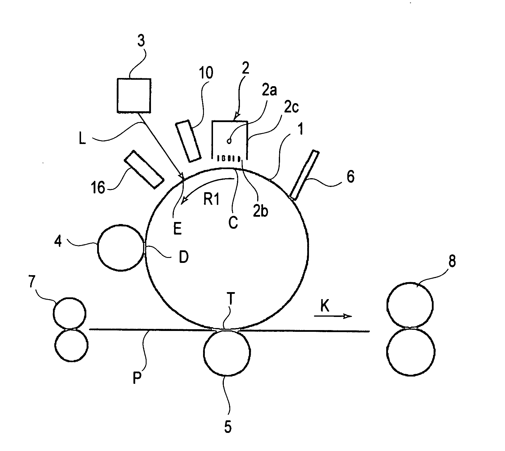
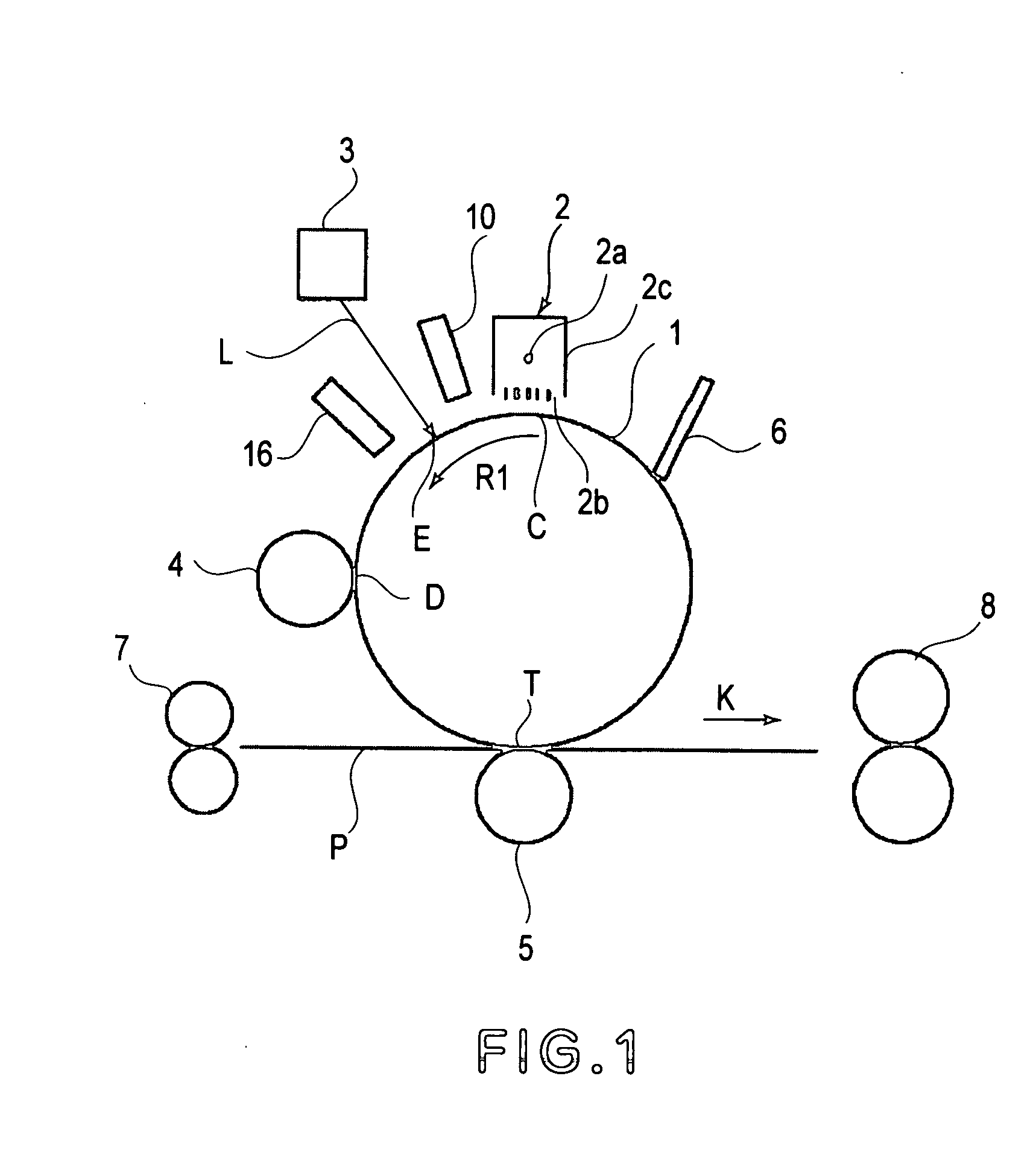
[0044]FIG. 1 is a schematic drawing of a typical image forming apparatus to which the present invention is applicable. In this embodiment, the present invention regarding the correction of the photosensitive drum in the post-exposure potential level will be described with reference to an image forming apparatus of the background exposure type, which forms an image by exposing the numerous points of the peripheral surface of the photosensitive member, which correspond to the background portions of an intended image, with the beam of light modulated with digitally processed video signals. This method of fo...


PUM


Abstract

An image forming apparatus includes a rotatable image bearing member; charging means for electrically charging the image bearing member; exposure means for exposing the image bearing member charged by the charging means to light at an exposure position to form an electrostatic latent image; pre-exposure potential detecting means for detecting a potential on the image bearing member before exposure to the light, the pre-exposure potential detecting means being disposed at a position downstream of the charging means and upstream of the exposure position with respect to a rotational direction of the image bearing member; and potential adjusting means for adjusting the potential on the image bearing member before the exposure on the basis of an output of the potential detecting means, the potential adjusting means being disposed downstream of the pre-exposure potential detecting means and upstream of the exposure position with respect to the rotational direction of the image bearing member.

Description

FIELD OF THE INVENTION AND RELATED ART [0001] The present invention relates to an electrophotographic image forming apparatus such as a printer, a copying machine, a facsimileing machine, etc. [0002] The image forming operation of an electrophotographic image forming apparatus such as a printer, a copying machine, a facsimileing machine, etc., has been as follows: The data regarding the gradation of each of the picture elements obtained with the use of a predetermined image processing method are converted into optical signals. The optical signals are reflected by an optical scanning system comprising a rotating polygon mirror, etc., so that the charged peripheral surface of a photosensitive drum (photosensitive member) is raster scanned to remove the electric charge from the exposed points of the peripheral surface of the photosensitive drum. As a result, an electrostatic latent image is formed. [0003] After the formation of the electrostatic latent image, toner is adhered by a deve...

Claims


Application Information

Patent Timeline
IPC IPC(8): G03G21/00G03G15/00G03G15/02G03G15/04
CPCG03G15/0266
Inventor KITAJIMA, KENICHIRO
Owner CANON KK
Why Eureka
Try Eureka