Check patentability & draft patents in minutes with Patsnap Eureka AI!

Method and apparatus for determining the position of the tibial exit point of the anterior cruciate ligament

Active Publication Date: 2005-10-06
AESCULAP AG
View PDF5 Cites 86 Cited by
  • Summary
  • Abstract
  • Description
  • Claims
  • Application Information

AI Technical Summary

Benefits of technology

[0015] It is particularly advantageous if a position of the exit point in which the latter lies as far as possible in the front part of the region enclosed by the projected curve and as close as possible to the projected curve is selected. As a result, the tibial exit point is shifted as far as possible to the front side of the knee joint, that is in the anterior direction. This increases the stability of the knee joint. Nevertheless, contact with the bone tissue of the femur is avoided.
[0024] It is advantageous if the computer unit presents the projected curve and the region enclosed by it on an image display, also shows a displaceable image of a display element for the selected position of the exit point on this image display and stores the corresponding positional data for the selected position in a memory. In particular, the display element may have the form of a circle of a diameter corresponding to that of the implant used.

Problems solved by technology

With this method, however, it is only possible to optimize the position of the exit point on the femur side; this known method cannot help with the selection of the exit point of the implant on the tibia side.
A major problem when determining the position of the exit point on the tibia side is that, when it is in the fitted state, the implant must remain free between the two exit points in all positions of the knee; it must therefore not be in contact with bone structures, for example specific surfaces of the femur, since this contact could lead to the implant being damaged.
Up until now, the surgeon has chosen the positioning of the tibial exit point of the anterior cruciate ligament on the basis of his experience, but misplaced implantations cannot in this case be ruled out with certainty.

Method used


Image

  • Method and apparatus for determining the position of the tibial exit point of the anterior cruciate ligament
  • Method and apparatus for determining the position of the tibial exit point of the anterior cruciate ligament
  • Method and apparatus for determining the position of the tibial exit point of the anterior cruciate ligament

Examples


Embodiment Construction

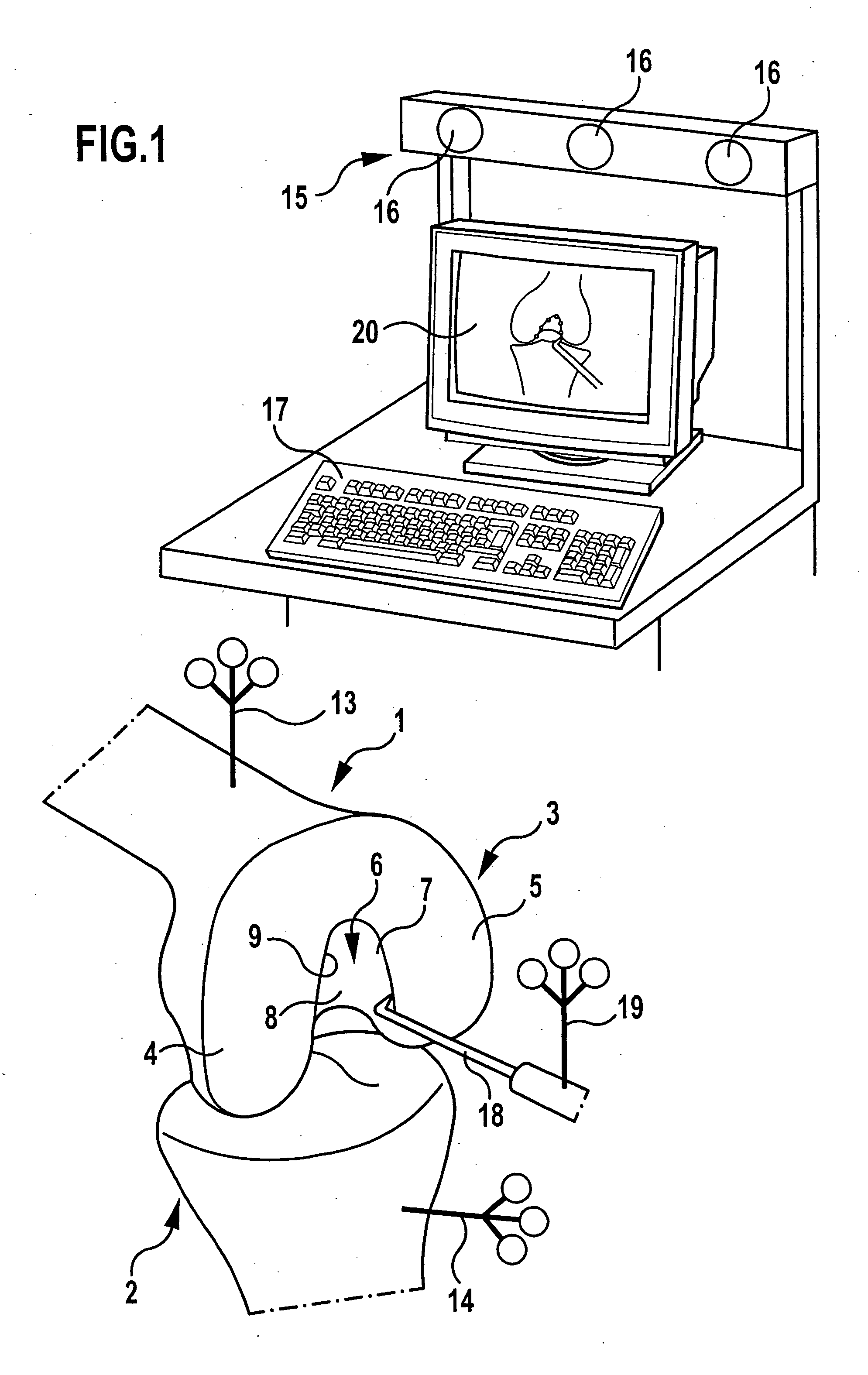
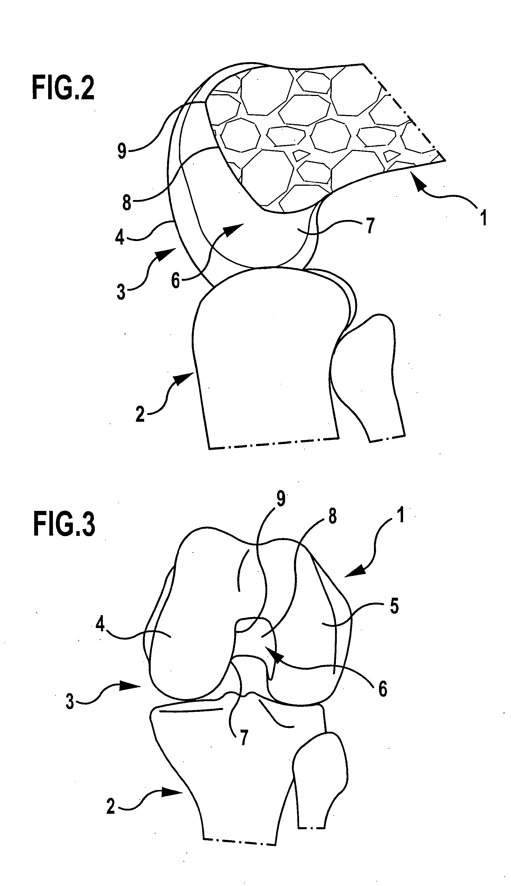
[0031] Represented in the drawing are the distal end of a femur 1 and the proximal end of a tibia 2, which together form a knee joint 3; the other parts of the knee joint have been omitted for clarity. In this region, the femur 1 forms two adjacent areas of the joint, the condyles 4, 5, which between them form a cavity. This cavity is usually referred to as the notch 6. This notch is bounded laterally by side surfaces 7 of the condyles 4, 5. On the upper side there extends a roof 8 running obliquely in relation to the longitudinal axis of the femur 1. On the front side, that is the anterior side, the notch 6 is closed, whereas to the rear side of the knee joint, that is the posterior side, it is open. Toward the areas of the joint that are the condyles 4, 5, the notch 6 is bounded by an approximately U-shaped front edge 9. This forms the transition between an osseous region and a cartilaginous region and is easy for the surgeon to feel and therefore locate.

[0032] The femur 1 and th...


PUM


Abstract

In order to establish an optimum position on the upper side of the tibia for the exit point of an anterior cruciate ligament replacement, it is proposed that, with the leg bent, the position of a number of points along the front edge of the notch is detected and in this way their position and progression on the femur are also determined, that, with the leg straight, the course of this front edge of the notch is projected onto a projection plane which is perpendicular to the longitudinal axis of the tibia in the region of the upper side of the tibia, and that, within the region enclosed by this projected curve, the exit point is selected such that it maintains at least a distance corresponding to the radius of the implant from the projected curve. Furthermore, an apparatus for carrying out such a method is proposed.

Description

[0001] This application is a continuation of international application number PCT / EP02 / 10861 filed on Sep. 27, 2002. [0002] The present disclosure relates to the subject matter disclosed in international application PCT / EP02 / 10861 of Sep. 27, 2002, which is incorporated herein by reference in its entirety and for all purposes.BACKGROUND OF THE INVENTION [0003] The invention relates to a method for determining the position on the upper side of the tibia of the exit point of an implant replacing the anterior cruciate ligament of a knee joint. The invention also relates to an apparatus for determining the position on the upper side of the tibia of the exit point of an implant replacing the anterior cruciate ligament of a knee joint, having a navigation system, having marking elements fixedly connected to the femur and the tibia, having a navigated sensor and having a data-processing system to which the positional data recorded by the navigation system can be fed. [0004] When replacing ...

Claims


Application Information

Patent Timeline
IPC IPC(8): A61B5/103G01S17/87A61B17/15A61B17/17A61B19/00
CPCA61B5/103A61B5/4533A61B17/154A61B17/155A61B17/157A61B17/1703A61B17/1714G01S17/87A61B5/6878A61B2034/2055A61B2034/2068A61B2034/2072A61B2090/061A61B2034/105A61B34/20
Inventor GIORDANO, NICOLALEITNER, FRANCOISBOUX DE CASSON, FRANCOISEICHHORN, JUERGEN
Owner AESCULAP AG
Features
  • R&D
  • Intellectual Property
  • Life Sciences
  • Materials
  • Tech Scout
  • Unparalleled Data Quality
  • Higher Quality Content
  • 60% Fewer Hallucinations
Learn More