Data transfer processing device and data transfer processing method

Inactive Publication Date: 2005-10-06
PANASONIC CORP
View PDF16 Cites 20 Cited by
  • Summary
  • Abstract
  • Description
  • Claims
  • Application Information

AI Technical Summary

Benefits of technology

[0012] Therefore, an object of the present invention is to provide a data transfer processing device and a data transfer processing me

Problems solved by technology

Therefore, the system buses cannot be used effectively, and thus this method lacks in practicability, for example, when a large amount of data is transferred.
It is necessary to gain or release the access right every time between a period during which data transfer is performed and a period during which data transfer is not performed in order to avoid this effect, but there is also the problem that when a device wa

Method used


Image

  • Data transfer processing device and data transfer processing method
  • Data transfer processing device and data transfer processing method
  • Data transfer processing device and data transfer processing method

Examples


Example

[0037] [First Embodiment]

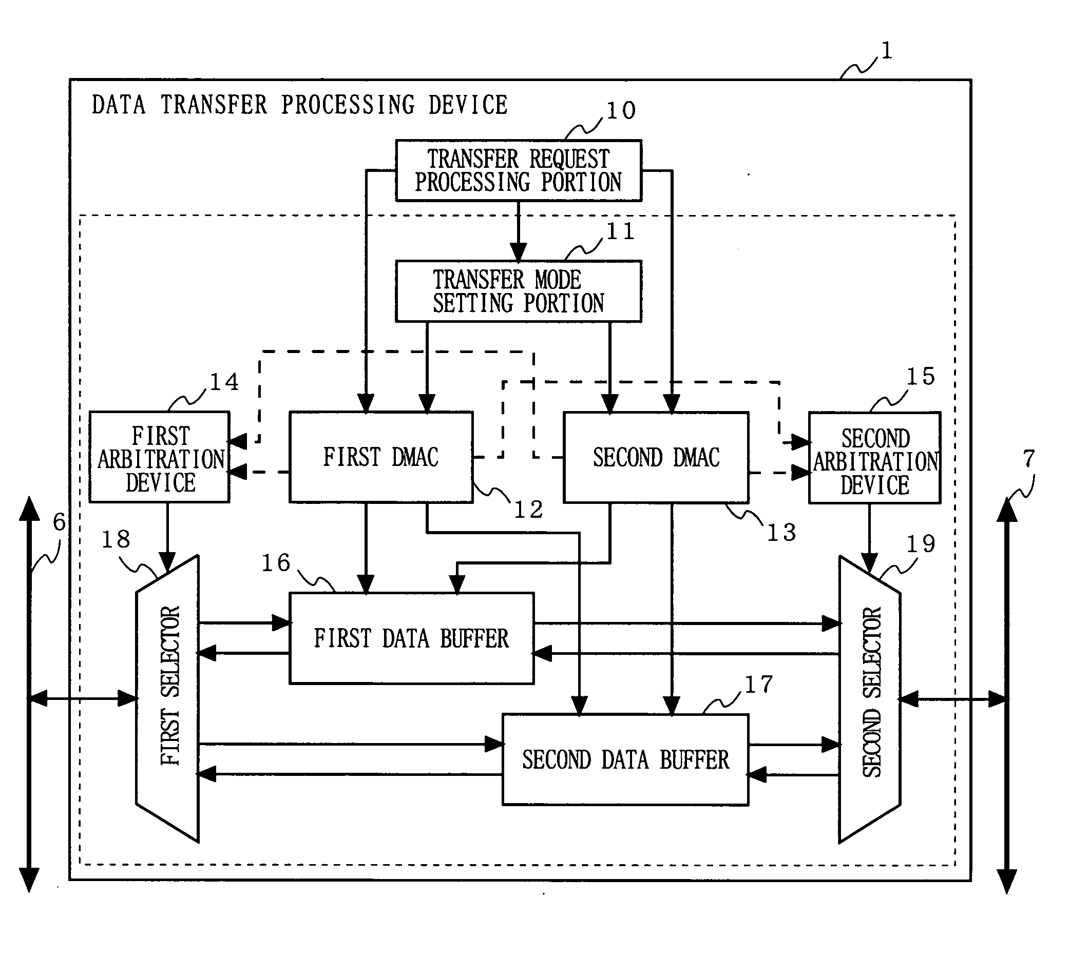
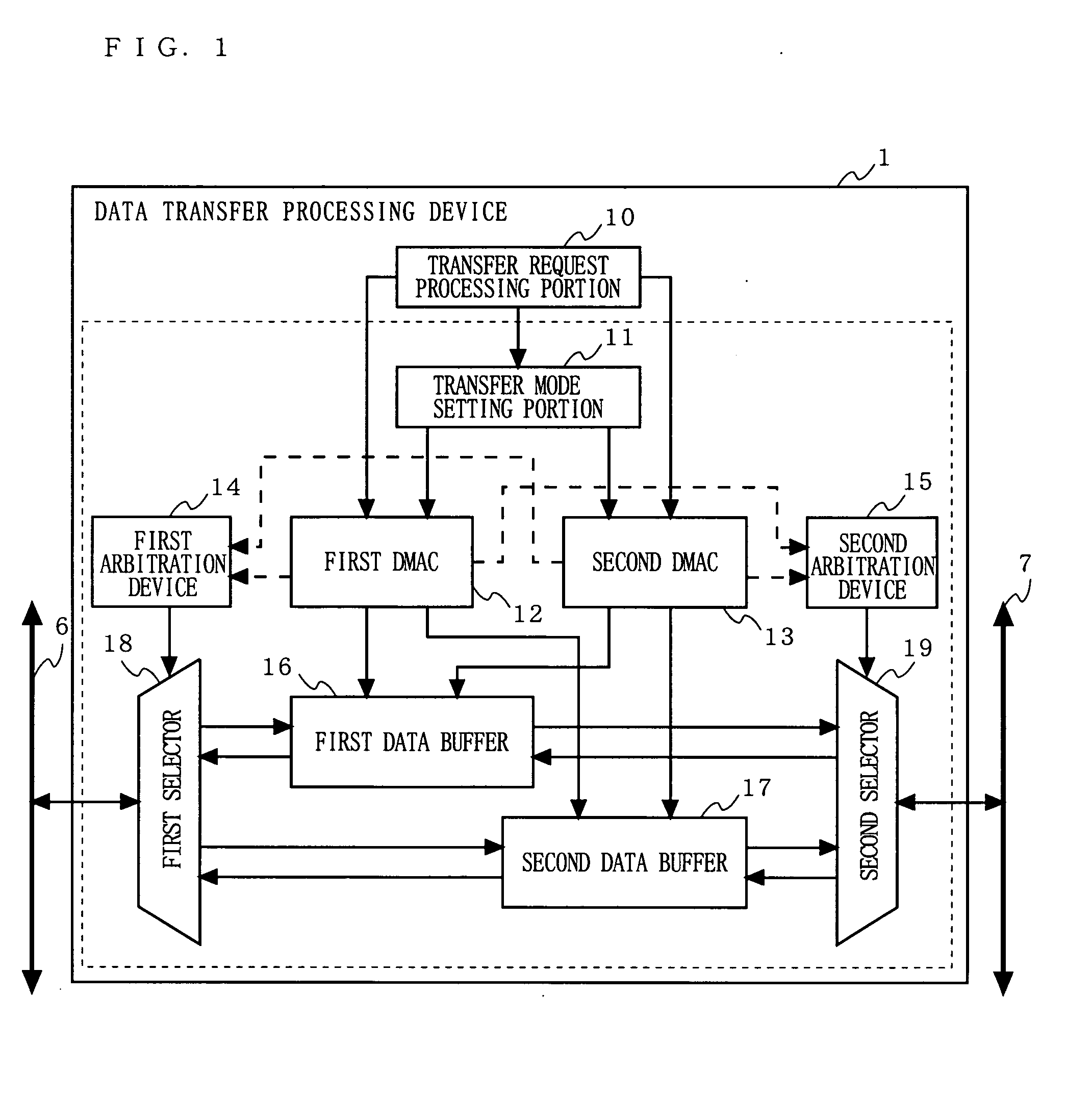
[0038]FIG. 1 is a block diagram showing the configuration of a data transfer processing device 1 according to a first embodiment of the present invention. In FIG. 1, the data transfer processing device 1 according to the first embodiment is provided with a transfer request processing portion 10, a transfer mode setting portion 11, a first DMAC 12, a second DMAC 13, a first arbitration device 14, a second arbitration device 15, a first data buffer 16, a second data buffer 17, a first selector 18, and a second selector 19. The data transfer processing portion 10 is connected to a first system bus 6 and a second system bus 7, and performs a data transfer process between the two system buses. The transfer request processing portion 10 is typically configured by, for example, a digital signal processor (DSP), a central processing unit (CPU), and a program memory (ROM), but the data transfer processing device of the present embodiment (and that of the following em...

Example

[0047] [Second Embodiment]

[0048]FIG. 4 is a block diagram showing the configuration of a data transfer processing device 2 according to a second embodiment of the present invention. In FIG. 4, the data transfer processing device 2 according to the second embodiment is provided with a transfer request processing portion 20, a status setting portion 21, a first DMAC 22, a second DMAC 23, a first arbitration device 14, a second arbitration device 15, a first data buffer 16, a second data buffer 17, a first selector 18, and a second selector 19. As shown in FIG. 4, the configuration of the data transfer processing device 2 according to the second embodiment is different from the configuration of the data transfer processing device 1 according to the first embodiment with regard to the transfer request processing portion 20, the status setting portion 21, the first DMAC 22, and the second DMAC 23. Hereinafter, the data transfer processing device 2 according to the second embodiment will ...

Example

[0055] [Third Embodiment]

[0056]FIG. 6 is a block diagram showing the configuration of a data transfer processing device 3 according to a third embodiment of the present invention. In FIG. 6, the data transfer processing device 3 according to the third embodiment is provided with a transfer request processing portion 20, a status setting portion 21, a first DMAC 32, a second DMAC 33, a first arbitration device 14, a second arbitration device 15, a first data buffer 16, a second data buffer 17, a first selector 18, a second selector 19, a data buffer arbitration control portion 30, a first data buffer status flag 34, and a second data buffer status flag 35. As shown in FIG. 6, the configuration of the data transfer processing device 3 according to the third embodiment is different from the configuration of the data transfer processing device 2 according to the second embodiment with regard to the first DMAC 32, the second DMAC 33, the data buffer arbitration control portion 30, the fi...


PUM


Abstract

A transfer request processing portion 10 confirms the kind of requested data and sets, in a transfer mode setting portion 11, a transfer mode for respectively allocating a first data buffer 16 to a first DMAC 12 and a second data buffer 17 to a second DMAC 13 when parallel data transfer is necessary, or a transfer mode for allocating both of the first data buffer 16 and the second data buffer 17 to the first DMAC 12 or the second DMAC 13 that has been started at that time when parallel data transfer is not necessary. The first DMAC 12 and/or the second DMAC 13 performs data transfer by using the data buffer instructed by the transfer mode.

Description

BACKGROUND OF THE INVENTION [0001] 1. Field of the Invention [0002] The present invention relates to a data transfer processing device and a data transfer processing method. In particular, the present invention relates to a data transfer processing device (for example, a bus bridge) and a data transfer processing method for performing data transfer between a plurality of system buses operating under different protocols or frequencies by direct memory access (DMA) transfer. [0003] 2. Description of the Background Art [0004]FIG. 12 shows an example of the configuration of a conventional data transfer processing device based on DMA transfer. In FIG. 12, a conventional data transfer processing device 101 is provided with a transfer request processing portion 110, a first direct memory access controller (DMAC) 112, a second DMAC 113, a first arbitration device 114, a second arbitration device 115, a first data buffer 116, a second data buffer 117, a first selector 118, and a second selec...

Claims


Application Information

Patent Timeline
IPC IPC(8): G06F13/40G06F13/28G06F13/36G06F13/38
CPCG06F13/28G06F13/405
Inventor KOTANI, ATSUSHI
Owner PANASONIC CORP
Why Eureka
Try Eureka