
Disk clamper and method of assembling the same

a technology of clamping device and clamping device, which is applied in the field of clamping device and assembling device, can solve the problems of difficult release of the engagement between the two, and achieve the effects of increasing the mating surface, reducing the deformation, and increasing the thickness of the first and second peripheral walls

Active Publication Date: 2005-10-06
MITSUBISHI ELECTRIC CORP
View PDF9 Cites 11 Cited by
  • Summary
  • Abstract
  • Description
  • Claims
  • Application Information

AI Technical Summary

Benefits of technology

[0007] The present invention is intended to solve the above described problems, and an object of the present invention is to provide a disk clamper and an assembling method thereof capable of enhancing the coupling strength between a clamper main body and a lid body, and preventing the separation of the main body and the lid body even when the impact force is applied because of the dropping or the like.
[0009] One of the first and second peripheral walls is fitted to the outside or inside of the other, and the first and second engaging members engage each other in the axial direction when the first and second peripheral walls are in the predetermined relative positions. Therefore, the clamper main body and the lid body can be integrated by fitting the first and second peripheral walls to each other in a state where the circumferential positions of the first and second engaging members are different from each other, and by rotating the first and second peripheral walls relative to each other until the first and second engaging members engage each other. Because it is not necessary to resiliently deform the first and second engaging claws, it is possible to increase the mating surfaces of the first and second engaging claws and therefore the engagement therebetween is not easily released. Further, it is also possible to increase the thicknesses of the first and second peripheral walls so as to restrict the deformations of first and second peripheral walls. Thus, it is possible to enhance the coupling strength between the clamper main body and the lid body, and therefore it is possible to prevent the separation of the clamper main body and the lid body even when the impact force is applied to the disk drive device due to the dropping of the disk drive device or the like.

Problems solved by technology

Because it is not necessary to resiliently deform the first and second engaging claws, it is possible to increase the mating surfaces of the first and second engaging claws and therefore the engagement therebetween is not easily released.

Method used


Image

  • Disk clamper and method of assembling the same
  • Disk clamper and method of assembling the same
  • Disk clamper and method of assembling the same

Examples


embodiment 1

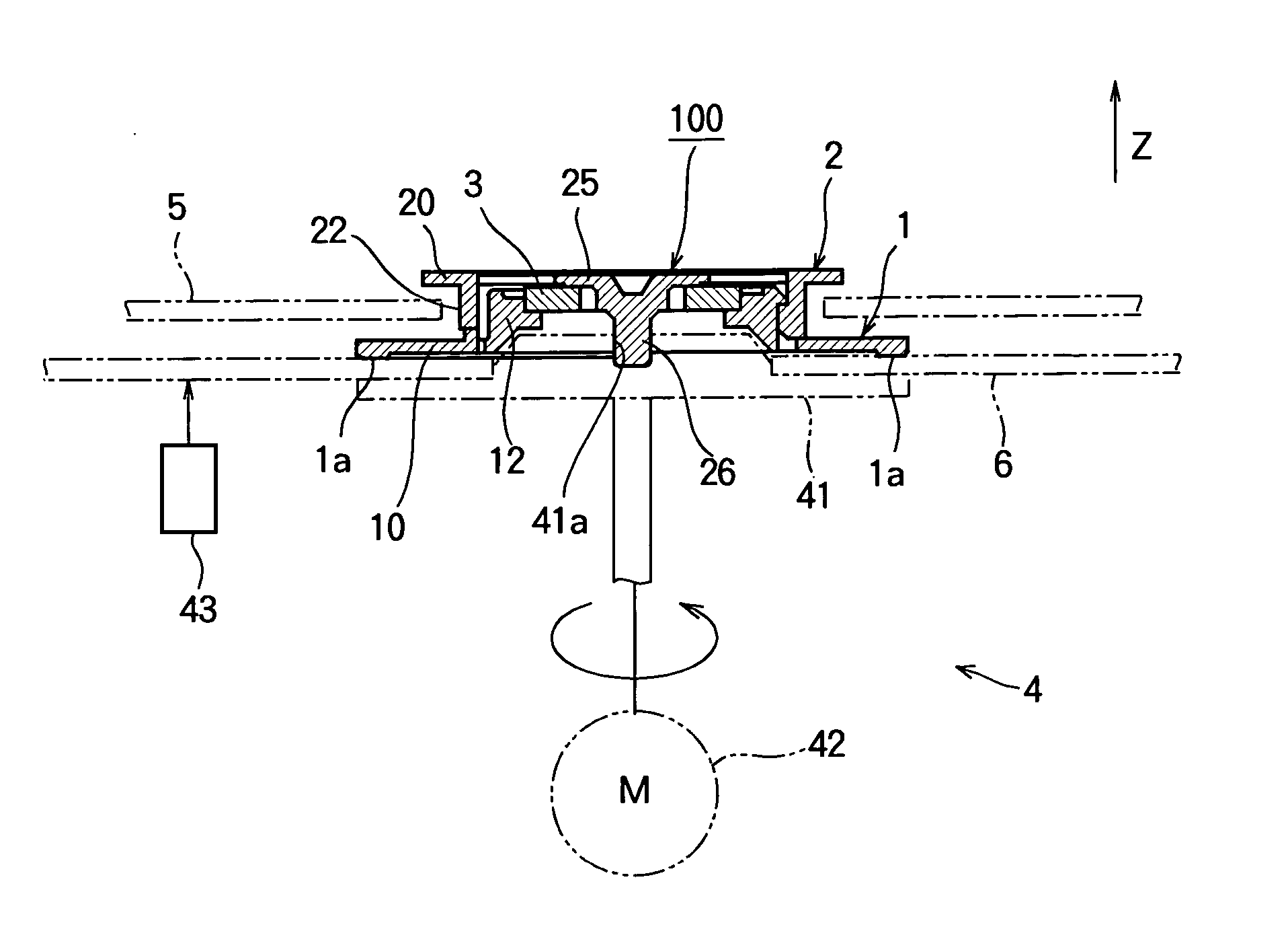
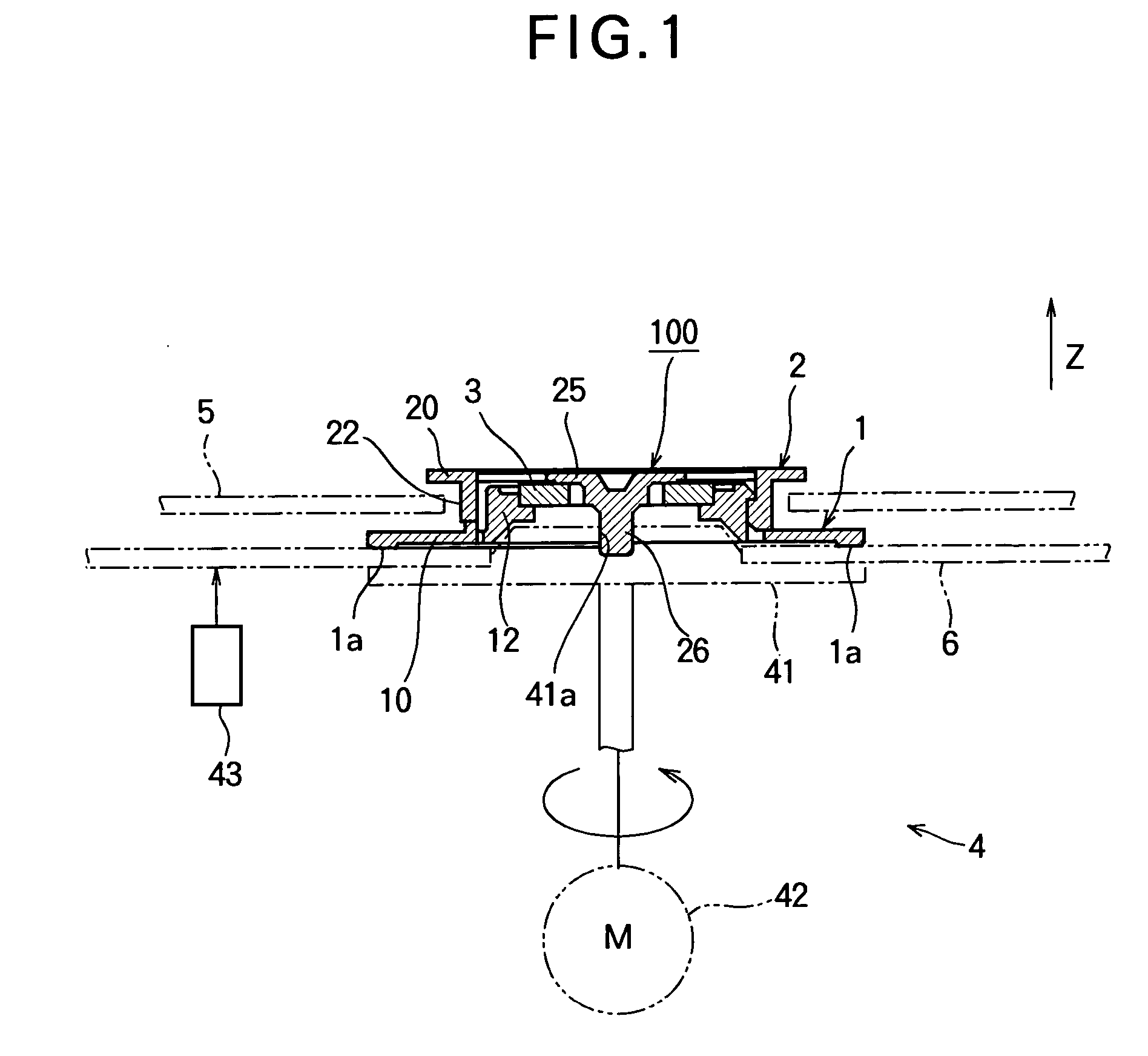
[0025]FIG. 1 is a schematic view of a disk drive device on which a disk clamper 100 according to Embodiment 1 of the present invention is mounted. The disk drive device includes a turntable 41 on which a disk 6 is placed, a spindle motor 42 for rotating the turntable 41, and a pickup 43 for writing information on and / or reading information from the disk 6. The disk clamper 100 holds the disk 6 so that the disk clamper 100 and the turntable 41 sandwich the disk 6 therebetween.

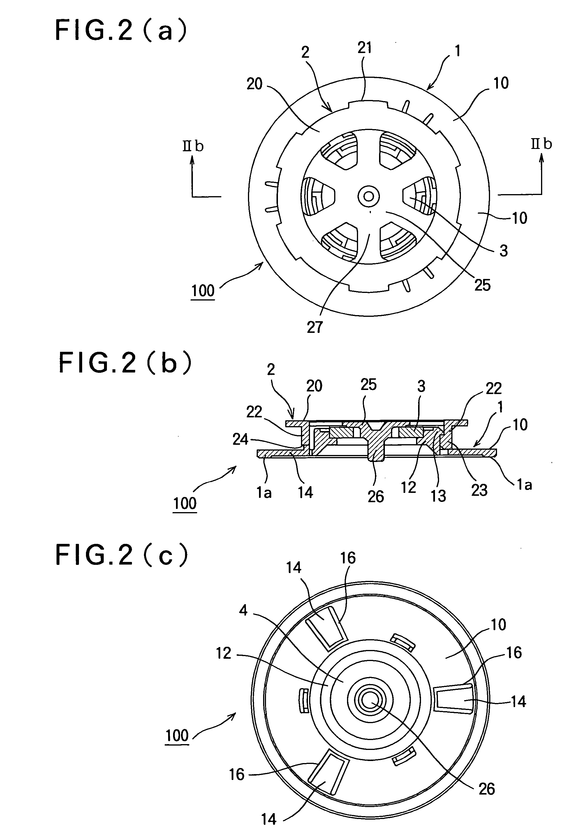
[0026]FIG. 2(a) is a plan view of the disk clamper 100. FIG. 2(b) is a sectional view taken along line IIb-IIb in FIG. 2(a). FIG. 2(c) is a bottom view of the disk clamper 100. As shown in FIGS. 2(a) through (c), the disk clamper 100 includes a clamper main body 1 having a disk contact surface 1a that contacts the surface of the disk 6, and a lid body 2 attached to the clamper main body 1. A ring-shaped attraction member 3 is held between the clamper main body 1 and the lid body 2.

[0027]FIG. 3(a) is a plan vie...

embodiment 2

[0050]FIG. 13 is a perspective view of a clamper main body 1 of a disk clamper according to Embodiment 2 of the present invention. In the disk clamper according to Embodiment 2, protrusions 7 are formed on the peripheral wall 12 of the clamper main body 1, each of which extends toward the base portion 10 from an end of each engaging claw 13 in the circumferential direction. The protrusions 7 function as stoppers (regulation means) that abut against the engaging claws 23 of the lid body 2 (FIG. 7). The other components are the same as those in Embodiment 1.

[0051] In order to integrate the clamper main body 1 and the lid body 2, the lid body 2 (FIG. 7) is rotated in the direction indicated by an arrow R in FIG. 13 with respect to the clamper main body 1 until the engaging claws 23 (FIG. 7) of the lid body 2 and the engaging claws 13 of the clamper main body 1 engage each other in the axial direction. In this state, the engaging claws 23 of the lid body 2 abut against the protrusions ...


PUM

PropertyMeasurementUnit
lengthsaaaaaaaaaa
magneticaaaaaaaaaa
shapeaaaaaaaaaa

Abstract

A disk clamper (100) includes a clamper main body (1) and a lid body (2) that holds an attraction member (3) such as a magnet or the like between the clam main body (1) and the lid body (2). The clamper main body (1) includes a peripheral wall (12) whose outer peripheral surface constitutes a cylindrical surface. The lid body (2) includes a peripheral wall (22) fitted on the outside of the peripheral wall (12) of the clamper main body (1). Engaging claws (13) are formed on and protruded from the outer peripheral surface of the peripheral wall (12). Engaging claws (23) are formed on the inner peripheral surface of the peripheral wall (22). The clamper main body (1) and the lid body (2) can be integrated by fitting the peripheral wall (22) to the outside of the peripheral wall (12) in a state where the circumferential positions of the engaging claws. (13, 23) are different from each other, and by rotating the peripheral walls (12, 22) relative to each other until the engaging members (13, 23) engage each other in the axial direction.

Description

TECHNICAL FIELD [0001] This invention relates to a disk clamper that holds a disk (such as a compact disk) between the disk clamper and a turntable to thereby rotate the disk, and relates to an assembling method of the disk clamper. BACKGROUND ART [0002] A disk clamper has an internal magnet for attracting a magnetic body or the like mounted on a turntable, in order that the disk clamper and the turntable hold the disk by sandwiching the disk therebetween. Therefore, the disk clamper is so constructed that a clamper main body and a lid body hold the magnet or the like therebetween. Such a disk clamper is disclosed in Japanese Laid-Open Patent Publication No. 10-308047 (pages 3 to 4 and FIG. 1). [0003] In the conventional disk clamper, a cylindrical member (a lid cylinder) provided on the lid body is fitted in the inside of a cylindrical member (a holding cylinder) provided on the clamper main body. Claws are integrally formed on a cylindrical wall of the lid cylinder, and the claws ...

Claims


Application Information

Patent Timeline
Patent Type & Authority Applications(United States)
IPC IPC(8): G11B17/028
CPCG11B17/0284
Inventor FUKASAWA, AKIHIRO
Owner MITSUBISHI ELECTRIC CORP
Learn More