Cooling apparatus of cooking appliance

a technology of cooking appliances and cooling devices, which is applied in the direction of lighting and heating devices, domestic stoves or ranges, heating types, etc., can solve the problems of deteriorating and the above-described conventional cooling structure of the door b>10/b> is not suitable for cooking appliances, so as to achieve the effect of increasing the cooling efficiency of the door

Active Publication Date: 2005-10-13
LG ELECTRONICS INC
View PDF4 Cites 29 Cited by
  • Summary
  • Abstract
  • Description
  • Claims
  • Application Information

AI Technical Summary

Benefits of technology

[0027] The cooling apparatus of the cooking appliance of the present invention causes external air to be directly sucked into the cabinet through the d

Problems solved by technology

However, since the above-described conventional cooling structure of the cooking appliance is configured such that the air in the door 10 is sucked and discharged by means of a difference of velocities of the air discharged from the electric component chamber 3, in case that the quantity of the air current for cooling the door 10 is small and the blowing force of the fan 7 is deteriorated due to long

Method used


Image

  • Cooling apparatus of cooking appliance
  • Cooling apparatus of cooking appliance
  • Cooling apparatus of cooking appliance

Examples


Embodiment Construction

[0036] Now, preferred embodiments of the present invention will be described in detail with reference to the annexed drawings.

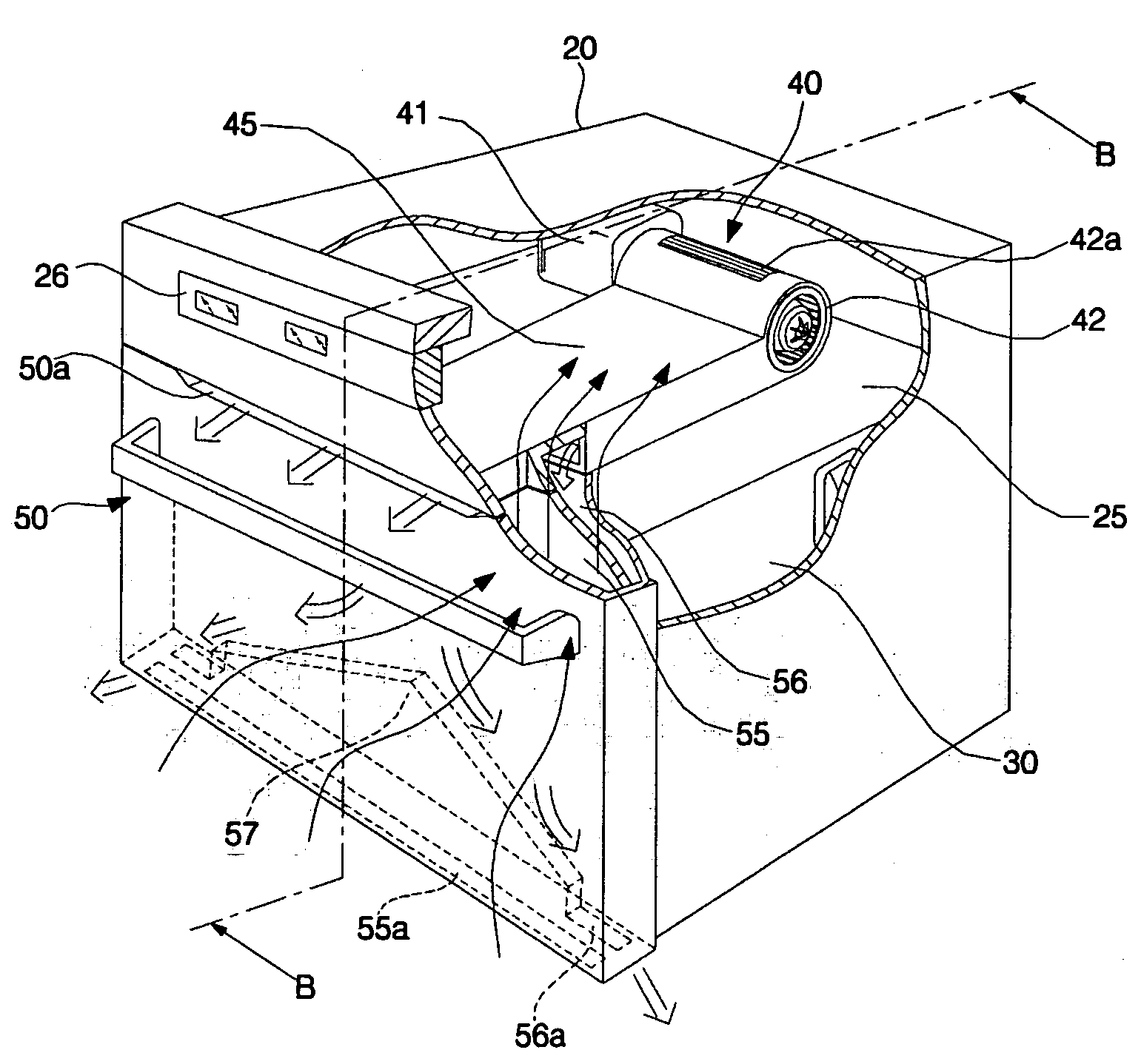
[0037]FIG. 3 is a partially exploded perspective view of a cooking appliance having a cooling apparatus in accordance with a first embodiment of the present invention, and FIG. 4 is a sectional view of FIG. 3, taken along line B-B.

[0038]FIG. 3 illustrates an oven provided with a cooling apparatus in accordance with the present invention. The oven comprises a cabinet 20 provided with a cooking chamber 30 heated by a heater and en electric component chamber 25 located on the upper part of the cooking chamber 30, a door 50 installed on the front surface of the cabinet 20 for opening and closing the cooking chamber 30, and an air blower 40 installed in the electric component chamber 25 in the cabinet 20 for sucking external air and then discharging the air so as to cool the door 50 and the inside of the electric component chamber 25.

[0039] Various electric com...


PUM


Abstract

A cooling apparatus of a cooking appliance including a cabinet having a cooking chamber located therein and an electric component chamber located outside the cooking chamber; a door installed on the cabinet for opening and closing the cooking chamber, and having a suction channel and a discharge channel communicating with the electric component chamber; and an air blower installed in the electric component chamber for sucking air to the inside of the electric component chamber through the suction channel and the discharge channel of the door and discharging the air, so that the external air having a low temperature is directly sucked through the door, cools the electric component chamber, and is then discharged to the outside, thereby increasing cooling efficiency of the door.

Description

BACKGROUND OF THE INVENTION [0001] 1. Field of the Invention [0002] The present invention relates to a cooling apparatus of a cooking appliance, such as an oven, and more particularly, to a cooling apparatus of a cooking appliance for cooling an electric component chamber and a door. [0003] 2. Description of the Related Art [0004]FIG. 1 is a partially exploded perspective view of a cooking appliance, particularly an oven, and FIG. 2 is a sectional view of FIG. 1, taken along line A-A. [0005] The oven as shown in FIG. 1 comprises a cabinet 1 having an opened front surface, a cooking chamber 2 installed in the cabinet 1 and heated such that food therein is cooked, a door 10 installed on the opened front surface of the cabinet 1 for opening and closing the cooking chamber 2, and an air blower 4 installed in an electric component chamber 3 located on the upper part of the cooking chamber 2 for cooling electric components in the cabinet 1. [0006] The cooking chamber 2 is heated by an ele...

Claims


Application Information

Patent Timeline
IPC IPC(8): F24C15/00F24C15/02F24C15/04F24C15/20
CPCF24C15/006F24C15/04B65G39/02B65G2207/08B65G2207/40
Inventor KIM, YANG KYEONGYANG, JAE KYUNGKIM, WAN SOOKIM, JONG SIK
Owner LG ELECTRONICS INC
Why Eureka
Try Eureka