Manufacturing method for a golf club head

a manufacturing method and golf club head technology, applied in the field of golf club head manufacturing method, can solve the problems of increased manufacturing cost and time, difficult machining, etc., and achieve the effect of increasing the overall quality of the golf club head

Inactive Publication Date: 2005-10-13
NELSON PRECISION CASTING
View PDF1 Cites 13 Cited by
  • Summary
  • Abstract
  • Description
  • Claims
  • Application Information

AI Technical Summary

Benefits of technology

[0011] The primary objective of this invention is to provide a manufacturing method for a golf club head which prefabricates an adhesive-filling groove between an opening of a main-body wax pattern and a striking-plate wax pattern. The adhesive-filling groove is filled with adhesive to combine the main-body wax pattern and the striking-plate wax pattern, and to form a smooth surface that may increase the overall quality of the golf club head. The manufacturing method for the golf club head in accordance with the present invention includes the steps of: prefabricating a main-body wax pattern and a striking-plate wax pattern, the main-body wax pattern providing with a rear opening and the striking-plate wax pattern providing with a stepped portion; initially combining the main-body wax pattern with the striking-plate wax pattern that remains an adhesive-filling groove between the rear opening of the main-body wax pattern and the stepped portion of the striking-plate wax pattern; filling adhesive into the adhesive-filling groove to constitute a combination member of the main-body wax pattern and the striking-plate wax pattern; immersing the combination member in slurry to form a ceramic shell and heating the ceramic shell for lost-wax processing; and pouring a melting alloy into the ceramic shell to form a club head casting.

Problems solved by technology

However, there are several drawbacks in manufacturing.
Certainly, it may result in difficulty of machining, and an increase of manufacturing cost and time.

Method used


Image

  • Manufacturing method for a golf club head
  • Manufacturing method for a golf club head
  • Manufacturing method for a golf club head

Examples


Embodiment Construction

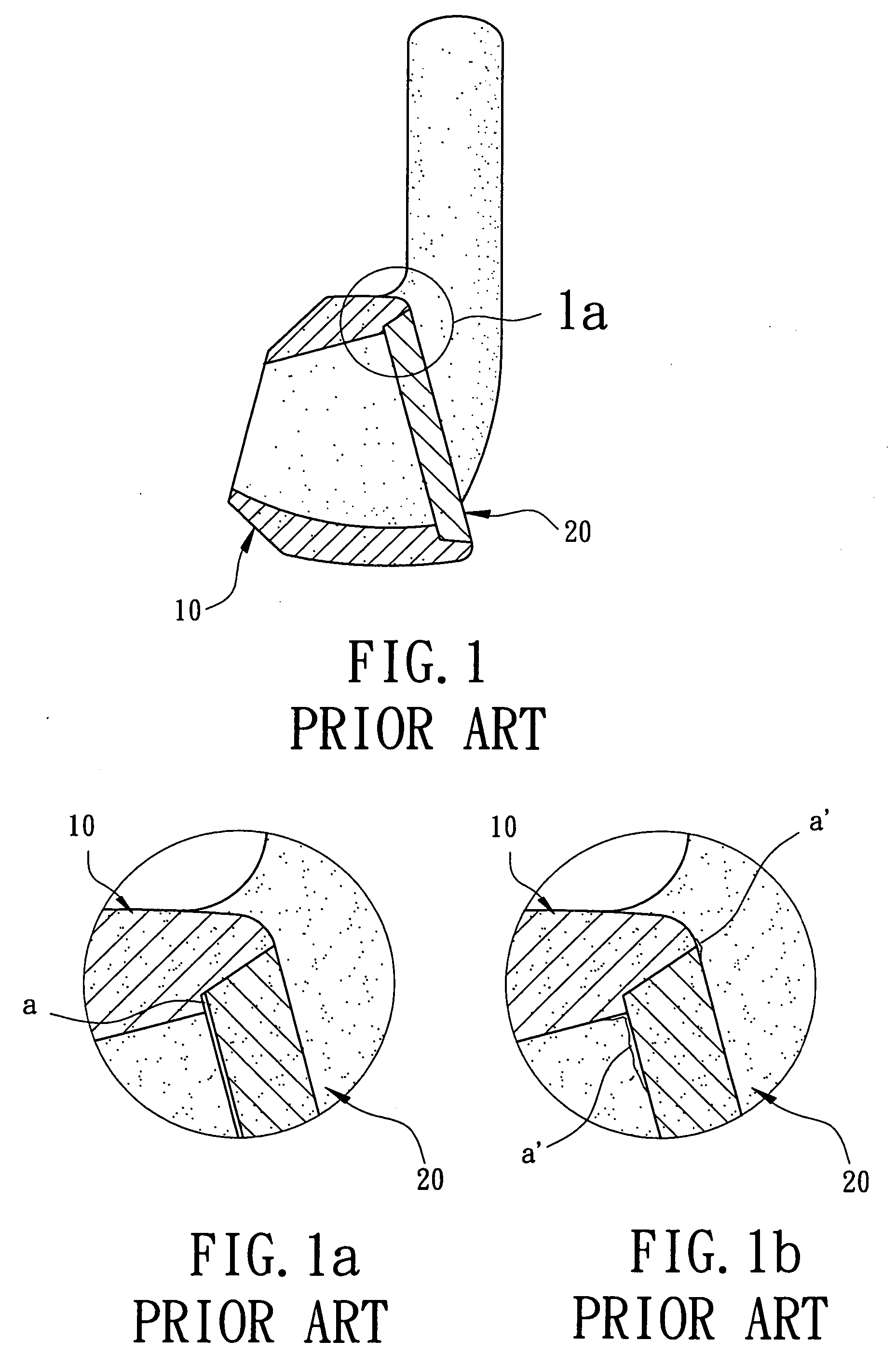
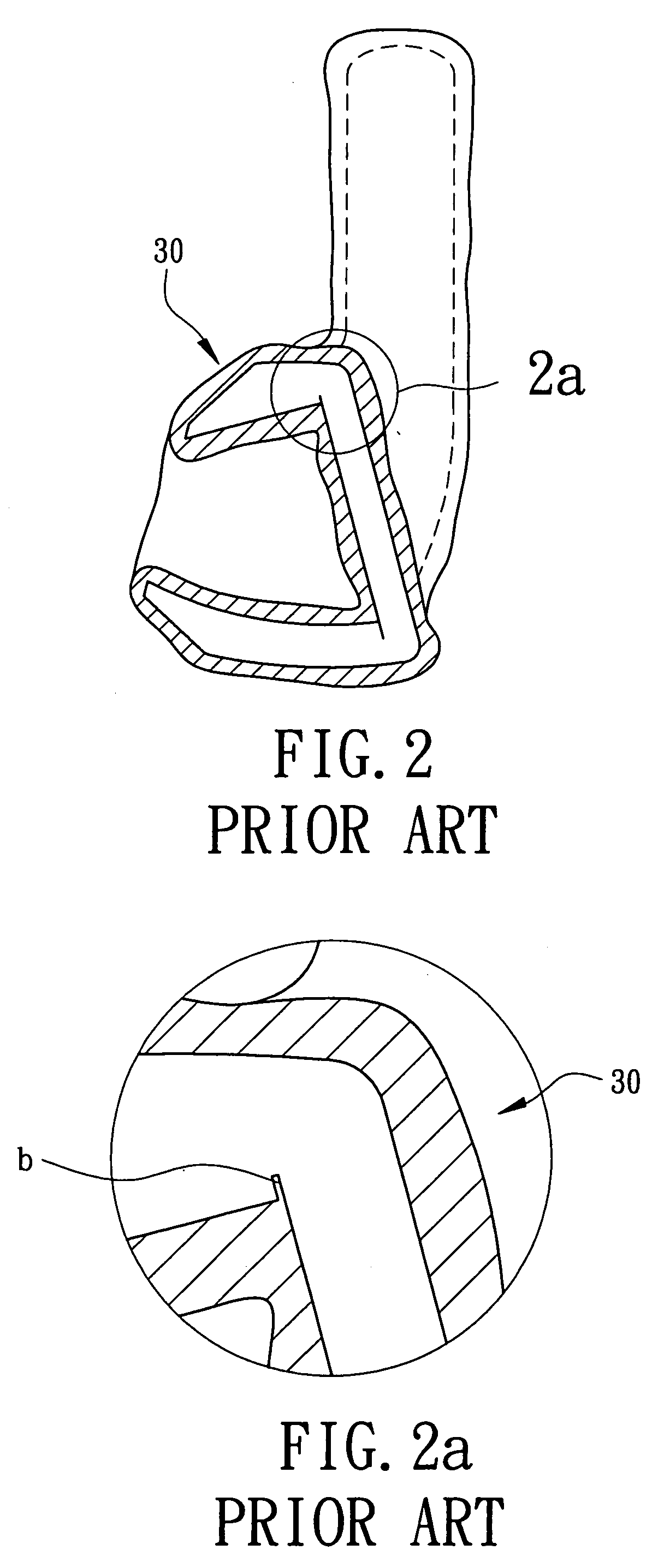
[0032] The reference numerals of the first and second embodiments of the present invention have applied the identical numerals of the conventional golf club head members, as shown in FIGS. 1 through 3. The construction of golf club head member members in accordance with embodiments of the present invention have similar configuration and same function as that of the conventional golf club head members and detailed descriptions may be omitted.

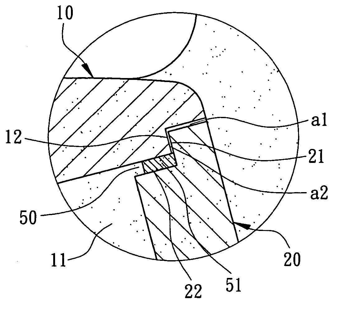
[0033] Referring to FIGS. 4 and 5, a first step of the manufacturing method for the golf club head in accordance with the first embodiment of the present invention prefabricates a main-body wax pattern 10 and a striking-plate wax pattern 20. The construction of the main-body wax pattern 10 provides with a rear opening 11 while that of the striking-plate wax pattern 20 providing with a stepped portion 21 at its rear side. First, wax liquid is injected into a mold assembly (not shown) for separately prefabricating the main-body wax pattern 10 and ...


PUM

PropertyMeasurementUnit
fluidityaaaaaaaaaa
thicknessaaaaaaaaaa
meltingaaaaaaaaaa

Abstract

A manufacturing method for a golf club head includes the steps of: prefabricating a main-body wax pattern and a striking-plate wax pattern, the main-body wax pattern providing with a rear opening and the striking-plate wax pattern providing with a stepped portion; initially combining the main-body wax pattern with the striking-plate wax pattern that remains an adhesive-filling groove between the rear opening of the main-body wax pattern and the stepped portion of the striking-plate wax pattern; filling adhesive into the adhesive-filling groove to constitute a combination member of the main-body wax pattern and the striking-plate wax pattern; immersing the combination member in slurry to form a ceramic shell and heating the ceramic shell for lost-wax processing; and pouring a melting alloy into the ceramic shell to form a club head casting.

Description

BACKGROUND OF THE INVENTION [0001] 1. Field of the Invention [0002] The present invention relates to a manufacturing method for a golf club head. More particularly, the present invention relates to the method of remaining an adhesive-filling groove between an opening of a main-body wax pattern and a striking-plate wax pattern and filling the groove with adhesive to form a smooth surface thereon. [0003] 2. Description of the Related Art [0004] Referring initially to FIGS. 1 through 3, Taiwanese Pat. Publication No. 514574 discloses a manufacturing method for a golf club head. The manufacturing method includes the steps of: 1[0005] 1. Separately prefabricating two wax patterns 10, 20, as shown in FIG. 1. Wax liquid is injected into a first mold assembly and a second mold assembly (not shown) to form two wax patterns 10, 20, such as a main-body wax pattern 10 and a striking-plate wax pattern 20. [0006] 2. Adhering the two wax patterns, as shown in FIG. 1. The two wax patterns 10, 20 ar...

Claims


Application Information

Patent Timeline
Patent Type & Authority Applications(United States)
IPC IPC(8): B22C7/02B22C7/00B22C9/04
CPCB22C7/02B22C9/04
Inventor HUANG, CHUN-YUNG
Owner NELSON PRECISION CASTING
Why Eureka
Try Eureka