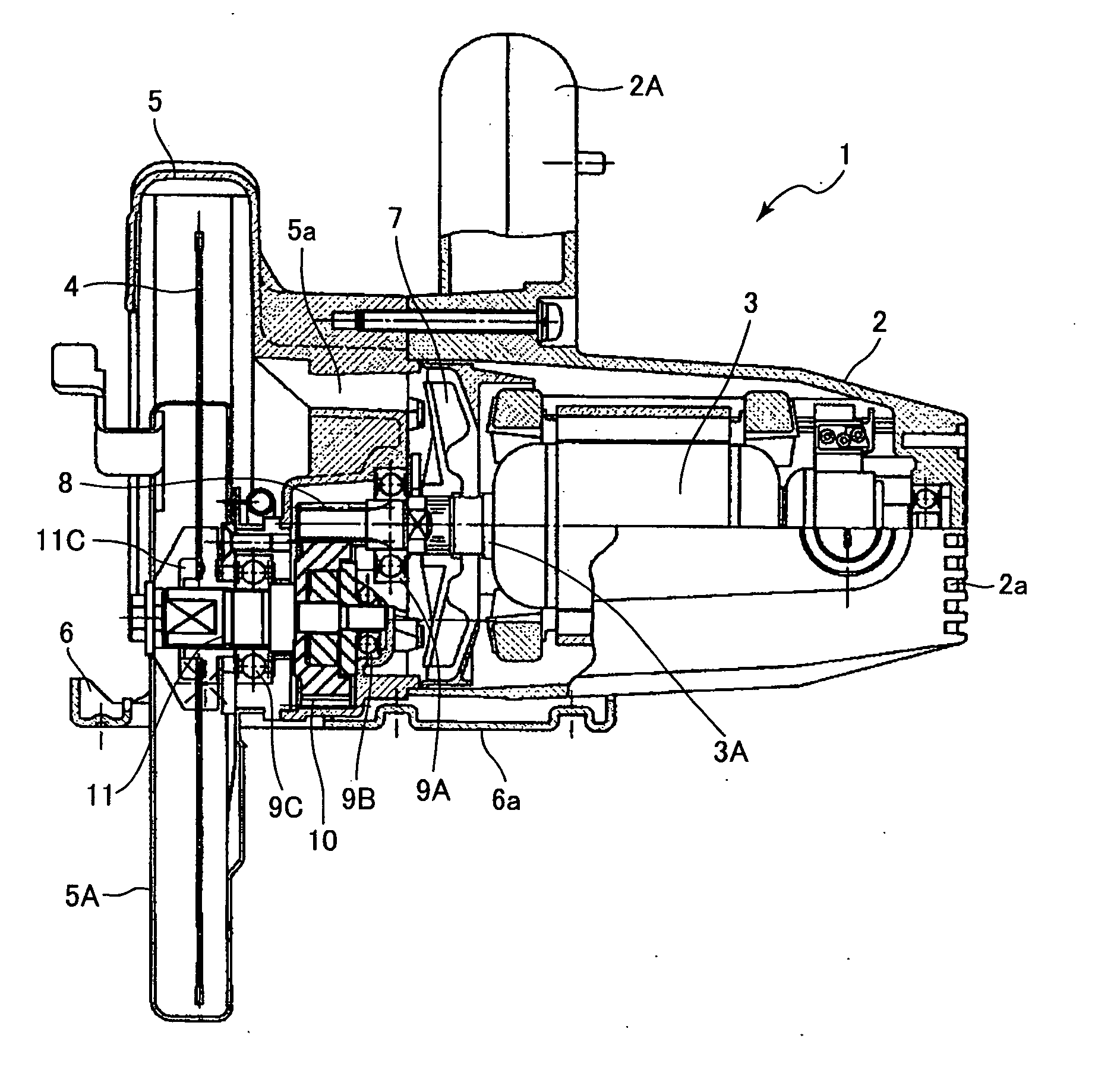
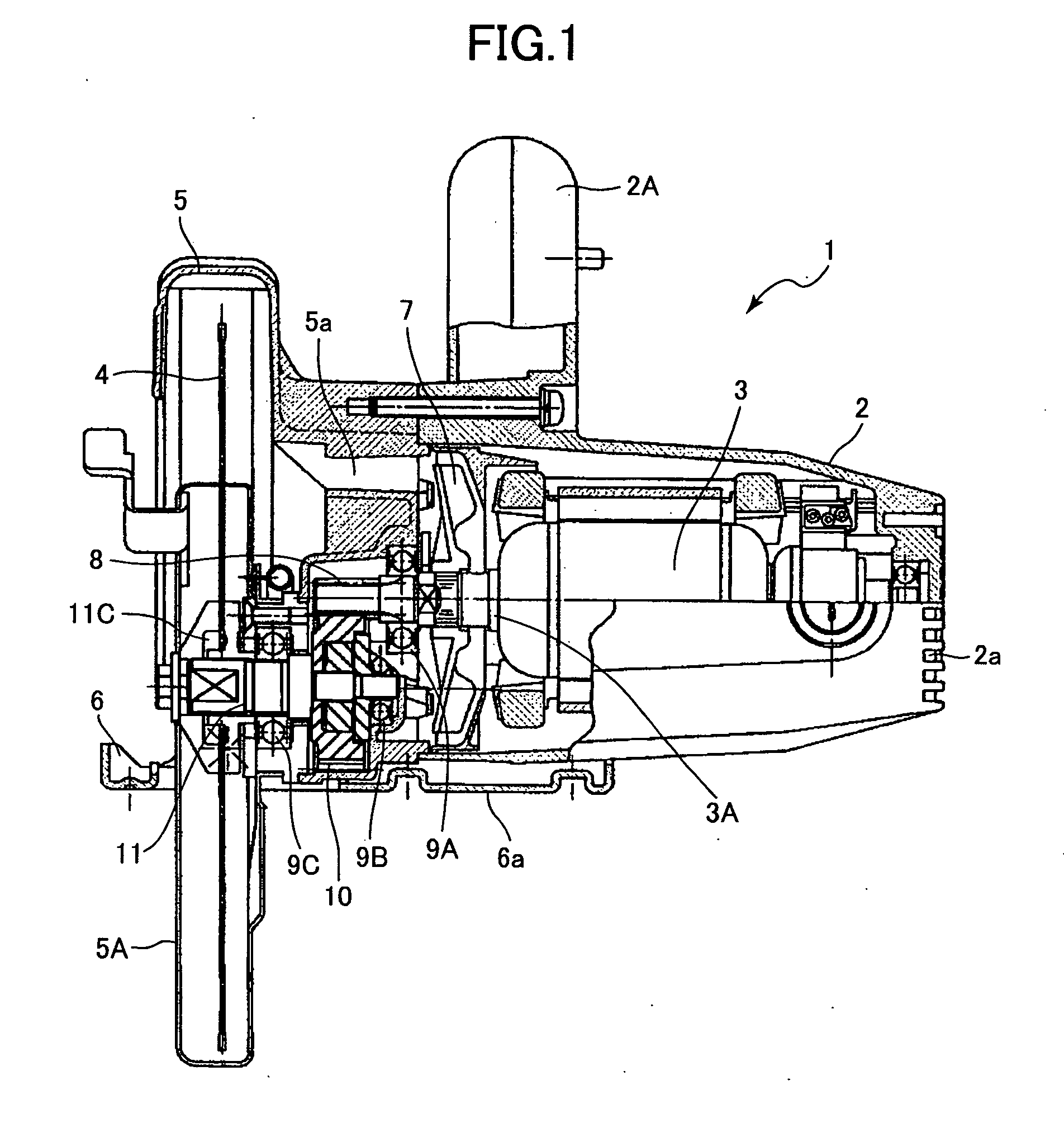
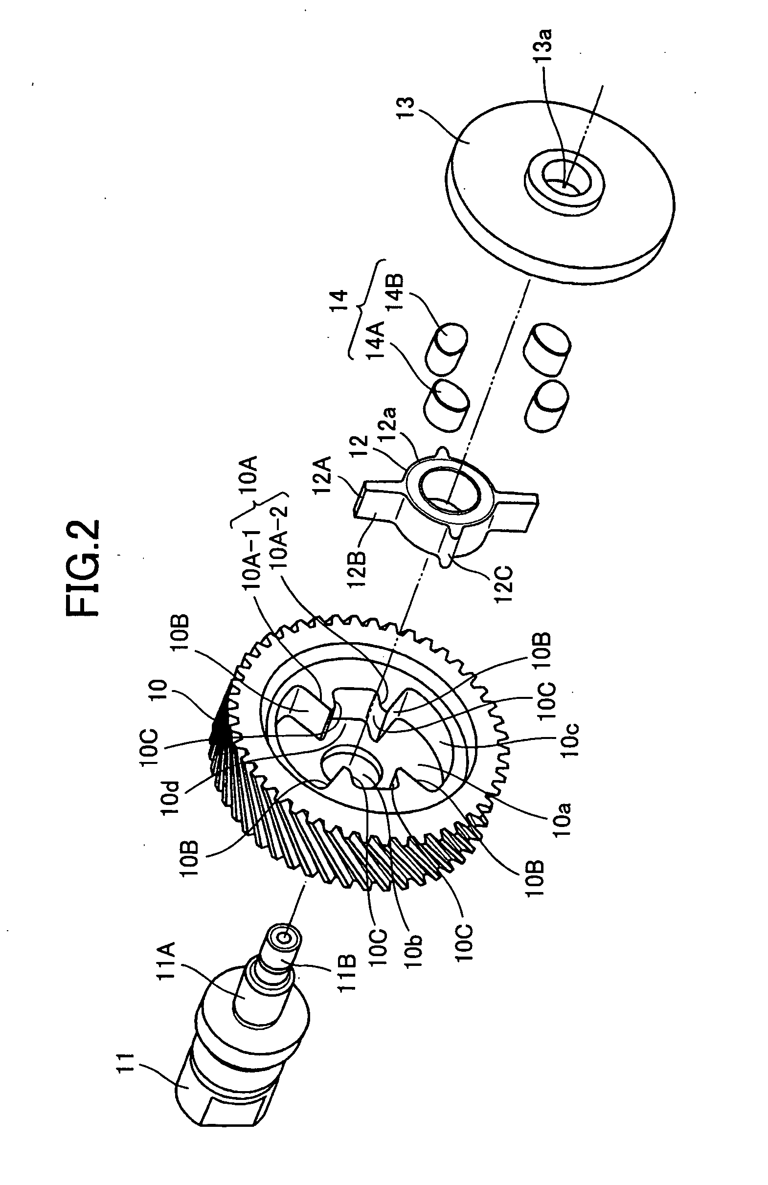
Power tool and gear unit assembled therein

a technology of power tools and gear units, which is applied in the direction of percussive tools, drilling pipes, wrenches, etc., can solve the problems of vibration force generating noise at the portions other than the gear parts, rotating fluctuation, and loud noise generation, so as to reduce the noise caused by gears, prolong the service life, and alleviate the effect of excessive load

Active Publication Date: 2005-10-13
KOKI HLDG CO LTD
View PDF21 Cites 25 Cited by
  • Summary
  • Abstract
  • Description
  • Claims
  • Application Information

AI Technical Summary

Benefits of technology

[0005] It is therefore, an object of the present invention to provide a power tool and a gear unit capable of reducing noise caused by gears and alleviating excessive load to be applied to gears thereby prolonging service life.
[0006] This and other objects of the present invention will be attained by a power tool including a housing, a motor, a gear unit, and a rotary shaft. The motor is disposed in the housing and has a drive shaft. The gear unit is supported in the housing and is driven by the drive shaft. The rotary shaft is rotatably supported to the housing and is driven through the gear unit. The gear unit includes an intermediate member and a gear. The intermediate member is force-fitted with the rotary shaft at a predetermined force-fitting pressure. The predetermined force-fitting pressure allows the rotary shaft and the intermediate member to rotate relative to each other when a load exceeding a predetermined load is applied between the rotary shaft and the intermediate member. The intermediate member has an abutment projection. The gear is driven by the drive shaft and is disposed concentrically with the rotary shaft and has a surround portion surrounding the intermediate member and provided with a convex portion. The surround portion is drivingly connected to the intermediate member to rotate the rotary shaft. The abutment projection is abuttable against the convex portion when the rotary shaft and the gear are rotated relative to each other.

Problems solved by technology

In a power tool, vibration force due to alternating current, pitch error and eccentricity of gears or the like cause rotational fluctuation.
Due to the rotational fluctuation, the tooth surfaces of gears on the drive shaft side and driven shaft side repeatedly bump against each other, thereby causing noise.
Further, the collision force between the tooth surfaces produces vibration force to generate noise at the portions other than gear parts.
Particularly loud noise is generated due to large impact force, since large torque is provided at the drive shaft side at an initial start-up period.
However, the steel key may be deformed due to long-term use thereby generating larger gap, which may adversely lead to noise.
However, the elastic member may be squashed and become ineffective when excessive load is applied between the drive shaft and drive gear.

Method used


Image

  • Power tool and gear unit assembled therein
  • Power tool and gear unit assembled therein
  • Power tool and gear unit assembled therein

Examples


first embodiment

[0045] In the elastic member 14 portions contacting the damper contact surfaces 10B and 12B are configured into an arcuate shape. Therefore, when no load is applied, a contact area of the elastic member 14 relative to the surfaces 10B, 12B is very small. However, the contact area is increased once load is applied to compress the elastic member 14.

[0046] The relationship between the rotation angle and the torque is represented in FIG. 5 in which a solid line curve represents a characteristic in a rubber A which is in accordance with the elastic member 14 of the first embodiment. One dotted chain line curve represents a characteristic in a comparative rubber B made from a material the same as that of the rubber A but has a rectangular solid shape so that a planer face is in contact with the damper contact surfaces 10B, 12B. Two dotted chain line curve represents a characteristic in a rubber C having the shape identical with that of the rubber B, but is made from a material having a s...

fourth embodiment

[0057] A gear unit according to the present invention is shown in FIGS. 9. The gear unit 300 includes a coupling 312 provided with a pair of damper projections 312A. The damper projections 312A also serve as abutment projections 312C abuttable on convex portions 310A corresponding to convex portions 10A, 110A and the wall 210A in the foregoing embodiments.

[0058] With this arrangement, the structure is simplified and the effect the same as that in the first and second embodiments can be obtained. Further, in the gear unit 300, the convex portion 310A is provided at position abuttable on only one side of the damper projection 312A.

[0059] This arrangement is advantageous in that the convex portion 310A is provided for the purpose of receiving greater load applying only in one direction to protect the elastic member 314A and to perform subsequent slippage between a first shaft section 311A and the coupling 312, whereas lesser load applying only in opposite direction is absorbed directl...

fifth embodiment

[0060] A gear unit according to the present invention is shown in FIGS. 10. The gear unit 400 includes a gear 410 formed with a concave portion 410a whose contour is defined by a wall 410B. The wall 410B includes a first flat wall 410B-1 and a second flat wall 410B-2 extending perpendicular thereto. A pair of convex 410A extends radially inwardly from the wall 410B. A coupling 412 is force-fitted with a first shaft section 411A of a spindle. The coupling 412 has a pair of radially outward projections 412A each formed with a pair of cut-away portions having a first flat surface 412B-1 and a second flat surface 412B-2 extending perpendicular thereto.

[0061] An elongated elastic member 414 is disposed between the first flat surface 412B-1 of the coupling 412 and the first flat wall 410B-1 of the gear 410. The elongated elastic member 414 is also disposed between the second flat surface 412B-2 of the coupling 412 and the second flat wall 410B-2 of the gear 410.

[0062] When the coupling 4...


PUM

PropertyMeasurementUnit
outer diameteraaaaaaaaaa
angleaaaaaaaaaa
pressureaaaaaaaaaa

Abstract

A power tool including a gear unit provided with a load moderating mechanism capable of reducing noise and prolonging service life. A coupling is force fitted with a spindle at a predetermined pressure allowing the spindle and the coupling to rotate relative to each other when a load exceeding a predetermined load is applied therebetween. A gear has a surround section having a convex and surrounding the coupling. The coupling has an abutment projection abutable against the convex and a damper projection. An elastic member is interposed between the damper projection and the surround section. Rotation of the gear is transmitted to the spindle through the elastic member and the coupling.

Description

BACKGROUND OF THE INVENTION [0001] The present invention relates to a power tool and a gear unit assembled therein. [0002] In a power tool, vibration force due to alternating current, pitch error and eccentricity of gears or the like cause rotational fluctuation. Due to the rotational fluctuation, the tooth surfaces of gears on the drive shaft side and driven shaft side repeatedly bump against each other, thereby causing noise. Further, the collision force between the tooth surfaces produces vibration force to generate noise at the portions other than gear parts. Particularly loud noise is generated due to large impact force, since large torque is provided at the drive shaft side at an initial start-up period. [0003] To avoid the above-described problem, improvement on dimension accuracy of the gear or on a design in shape of the tooth surface have been proposed. Further, in order to structurally reduce the noise, a gap is positively provided between a steel key and an inner periphe...

Claims


Application Information

Patent Timeline
Patent Type & Authority Applications(United States)
IPC IPC(8): B23B45/02B25B21/00B23D47/12B24B23/00B25B23/00B25D13/00B25F3/00B25F5/00F16D3/02F16D3/12F16D3/14F16D3/68F16D7/02F16F15/136F16H1/14
CPCB23D47/12B24B23/00B25F5/006F16D3/02F16D3/12F16D7/021Y10T74/19633
Inventor KAMIMURA, JUNICHIINAGAWA, HIROTOYOSHIDA, KENICHIROUKAWAMATA, TAKASHI
Owner KOKI HLDG CO LTD
Why Eureka
Try Eureka