Electric power steering apparatus

a technology of electric power steering and gear wheels, which is applied in the direction of elastic bearings, rigid support of bearing units, bearings, etc., can solve the problems of accelerated wear of worm gear surfaces, high manufacturing cost, and relatively high backlash rate after assembly, and achieves high precision in machining and increase manufacturing cost

Active Publication Date: 2005-10-13
NSK LTD
View PDF6 Cites 30 Cited by
  • Summary
  • Abstract
  • Description
  • Claims
  • Application Information

AI Technical Summary

Benefits of technology

[0015] The present invention has been made in view of the above-described circumstances. An object of the present invention is to provide an electric power steering apparatus in which the worm shaft can be tilted (or can swing) relative to the inner ring of the

Problems solved by technology

Conventionally, due to dimension errors of the worm, worm shaft, bearing portions for supporting it, worm wheel and steering shaft for supporting it that might occur in assembling the worm shaft and worm wheel, backlash occurs after assembly at a relatively high rate.
Thus, the assembly process is very complicated.
However, when high output steering assist forces have been achieved, as is the case in recent years, wear of the gear surfaces of the worm and the worm wheel is accelerated, and backlash occurs inevitably.
In that case, there is a risk that gear slapping soun

Method used


Image

  • Electric power steering apparatus
  • Electric power steering apparatus
  • Electric power steering apparatus

Examples


first embodiment

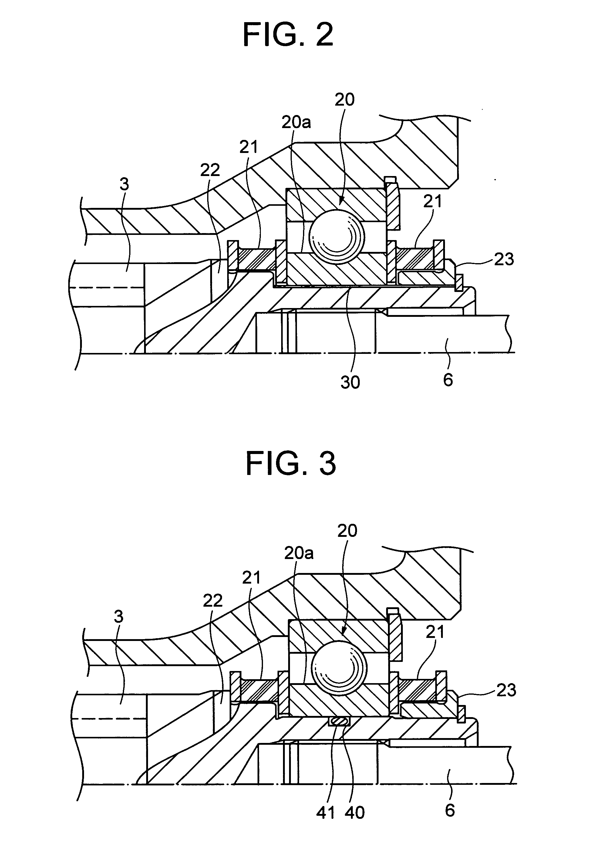
[0045]FIG. 2 is a cross sectional view showing a principal portion (corresponding to the encircled portion in FIG. 1) of the electric power steering apparatus according to the first embodiment of the a present invention.

[0046] A small gap is formed between the worm shaft 3 and the inner circumference of the inner ring 20a of the second bearing 20 so as to allow tilting of the worm shaft 3 relative to the inner ring 20a of the second bearing. With this feature, the worm shaft 3 can be tilted (or can swing) relative to the inner ring 20a of the second bearing 20 without fail upon application of preload by the torsion spring 14.

[0047] When the worm shaft 3 is tilted or displaced in the radial direction, a shearing stress is generated in the rubber damper 21 to create a reaction force acting to make it coaxial with the second bearing 20.

[0048] In at least portion of the small gap, there is provided a buffer member 30 for avoiding sound generated when the worm shaft 3 receives a radia...

second embodiment

[0050]FIG. 3 is a cross sectional view showing a principal portion (corresponding to the encircled portion in FIG. 1) of the electric power steering apparatus according to the second embodiment of the present invention.

[0051] In contrast to the first embodiment, a circumferential groove 40 is formed on the outer circumferential surface of the worm shaft 3 radially inside the inner ring 20a of the second bearing 20.

[0052] An O-ring 41 serving as an elastic member is fitted in the circumferential groove 40. The O-ring 41 is compressed between the inner ring 20a of the second bearing 20 and the worm shaft 3 to generate a repulsive force in response to radial displacement of worm shaft 3, the repulsive force being uniform all along the circumference. Thus, the worm shaft 3 can stay in a floating state relative to the inner ring 20a of the second bearing 20, so that the worm shaft 3 and the inner ring 20a of the worm shaft 3 will not come in contact with each other.

[0053] In connectio...

third embodiment

[0056]FIG. 4A is a cross sectional view showing a principal portion (corresponding to the encircled portion in FIG. 1) of the electric power steering apparatus according to the third embodiment of the present invention. FIG. 4B is a partial cross sectional view showing a circumferential groove, an elastic member and a solid lubricant.

[0057] In contrast to the second embodiment, an elastic member 51 is formed integrally with a solid lubricant 52, typified by Teflon (registered trademark), in a circumferential groove 50 formed on the outer circumferential surface of the worm shaft 3 radially inside the inner ring 20a of the second bearing 20.

[0058] Since friction between the worm shaft 3 and the inner ring 20a of the second bearing 20 is reduced by the solid lubricant 52, the worm shaft 3 can be shifted or tilted more smoothly. Thus, wear resistance is improved, and durability is enhanced.

[0059] The solid lubricant 52 may be formed integrally with the elastic member 51 on one of or...


PUM


Abstract

A small gap is formed between a worm shaft 3 and a second bearing 20, so that the worm shaft can be tilted relative to the inner ring 20a of the second bearing 20 without fail when preloaded by a torsion spring 14. An elastic member 41 is provided in at least portion of a circumferential groove 40 in the small gap. The worm shaft 3 and the inner ring 20a of the second bearing 20 are not in contact with each other, and their metallic clank in the small gap can be prevented. By providing a projecting portion(s) 3b on one side or both sides, with respect to the axial direction, of the circumferential groove 40, the small gap between the worm shaft 3 and the inner ring 20a of the second bearing 20 can be made large, and it is possible to enlarge the range over which the worm shaft 3 can swing.

Description

TECHNICAL FIELD [0001] The present invention relates to an electric power steering apparatus that generates assist steering torque by an electric motor in response to steering torque applied on the steering wheel and transmits the assist torque to an output shaft of a steering mechanism while reducing it by means of a reduction gear. BACKGROUND ART [0002] In a known electric power steering apparatus for a vehicle, rotational output of an electric motor for providing assist steering torque is transmitted, while reduced, to an output shaft of the steering apparatus by a gear apparatus to assist the steering force applied to the steering wheel in the wheel steering operation. In such an electric power steering apparatus, the power is transmitted to the output shaft while the rotation of the electric motor is reduced by a power transmission mechanism provided in a housing. [0003] In the electric power steering apparatus that utilizes the aforementioned power transmission mechanism in th...

Claims


Application Information

Patent Timeline
IPC IPC(8): B62D5/04F16C19/54F16C27/06F16C35/073F16H1/16
CPCB62D5/0409F16C19/54F16C27/066F16H1/16F16H57/0006F16H57/021F16H2057/0213F16H55/24F16C35/063F16C2361/61B62D5/04
Inventor SEGAWA, TORU
Owner NSK LTD
Why Eureka
Try Eureka