Apparatus and method for mode-switching fuel injector nozzle

a fuel injector and mode-switching technology, which is applied in the direction of fuel injecting pumps, machines/engines, electric control, etc., can solve the problems of in-cylinder conditions that are not typical of normal operation for fuel injector nozzles, and the inability of fuel injector nozzles to adapt to provide optimized fuel spray patterns

Inactive Publication Date: 2005-10-13
DELPHI INT OPERATIONS LUXEMBOURG S A R L
View PDF17 Cites 74 Cited by
  • Summary
  • Abstract
  • Description
  • Claims
  • Application Information

AI Technical Summary

Benefits of technology

[0008] In yet another exemplary embodiment, a fuel injector for dispersing fuel into a swirl chamber or pre-combustion chamber of a divided-chamber engine is provided. Here only one pair of openings is provided in the nozzle, the first opening being used for non-traditional cycles as described above, and also for cold starting and light load operation in which fuel is dispersed into the center of the pre-chamber where the air is hottest. Fuel from the second opening is dispersed to that part of the pre-chamber with high velocity air motion, and in the process the second spray inhibits penetration of the first spray.

Problems solved by technology

Typical fuel injector nozzles are configured such that fuel spray pattern, fuel atomization and fuel / air mixing are optimized for combustion during the most prevalent engine operating condition (e.g., normal Compression Ignition (CI) operation) however, EGA technologies and other emission reduction technologies require the fuel injector nozzles to operate at in-cylinder conditions untypical of normal operation.
Thus, fuel injector nozzles are currently not adaptable to provide optimized fuel spray patterns, fuel flow rates, fuel atomization and fuel / air mixtures of varying degrees for both “normal operation” and operations associated with non-traditional emission reduction cycles.

Method used


Image

  • Apparatus and method for mode-switching fuel injector nozzle
  • Apparatus and method for mode-switching fuel injector nozzle
  • Apparatus and method for mode-switching fuel injector nozzle

Examples


Embodiment Construction

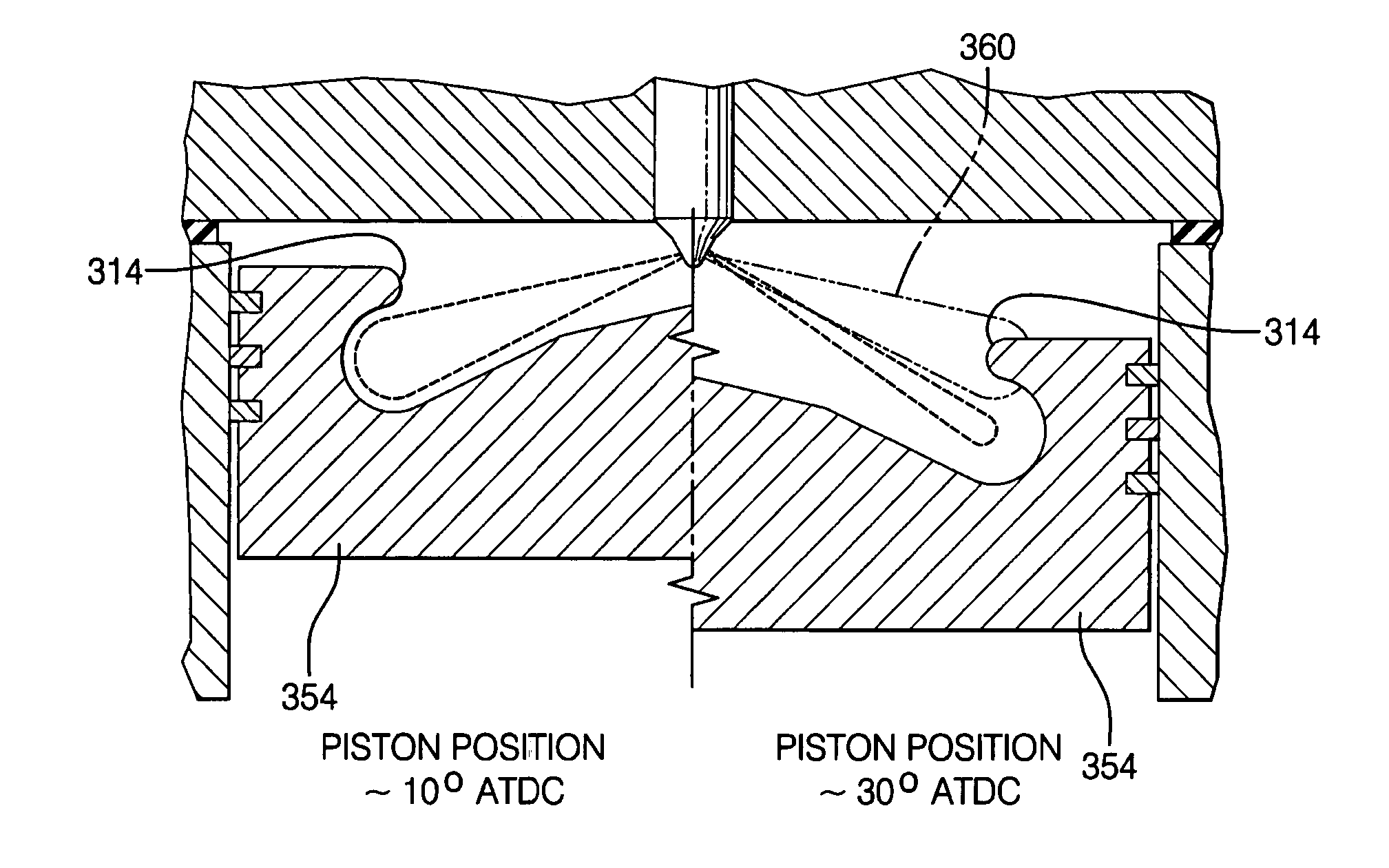
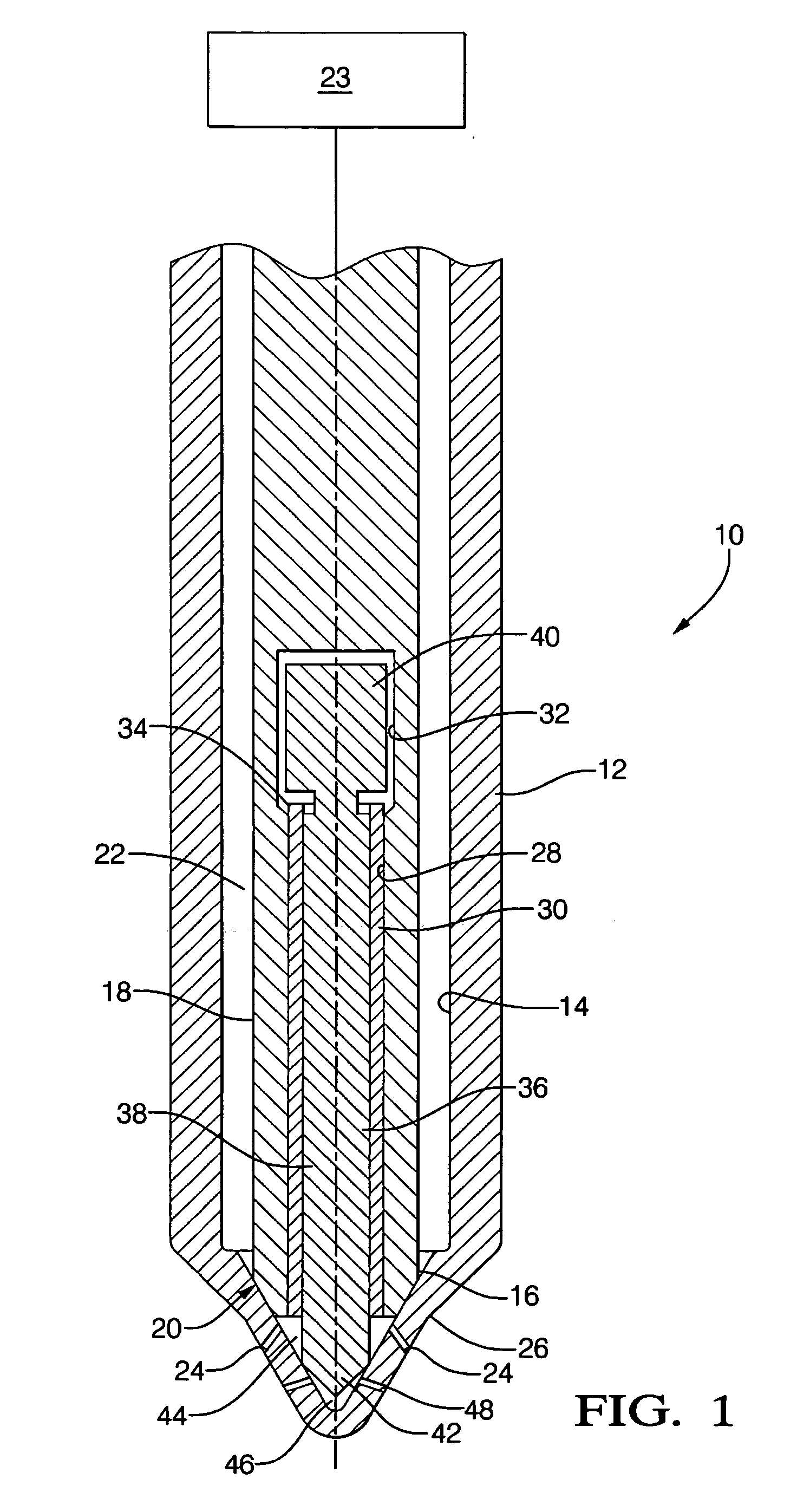
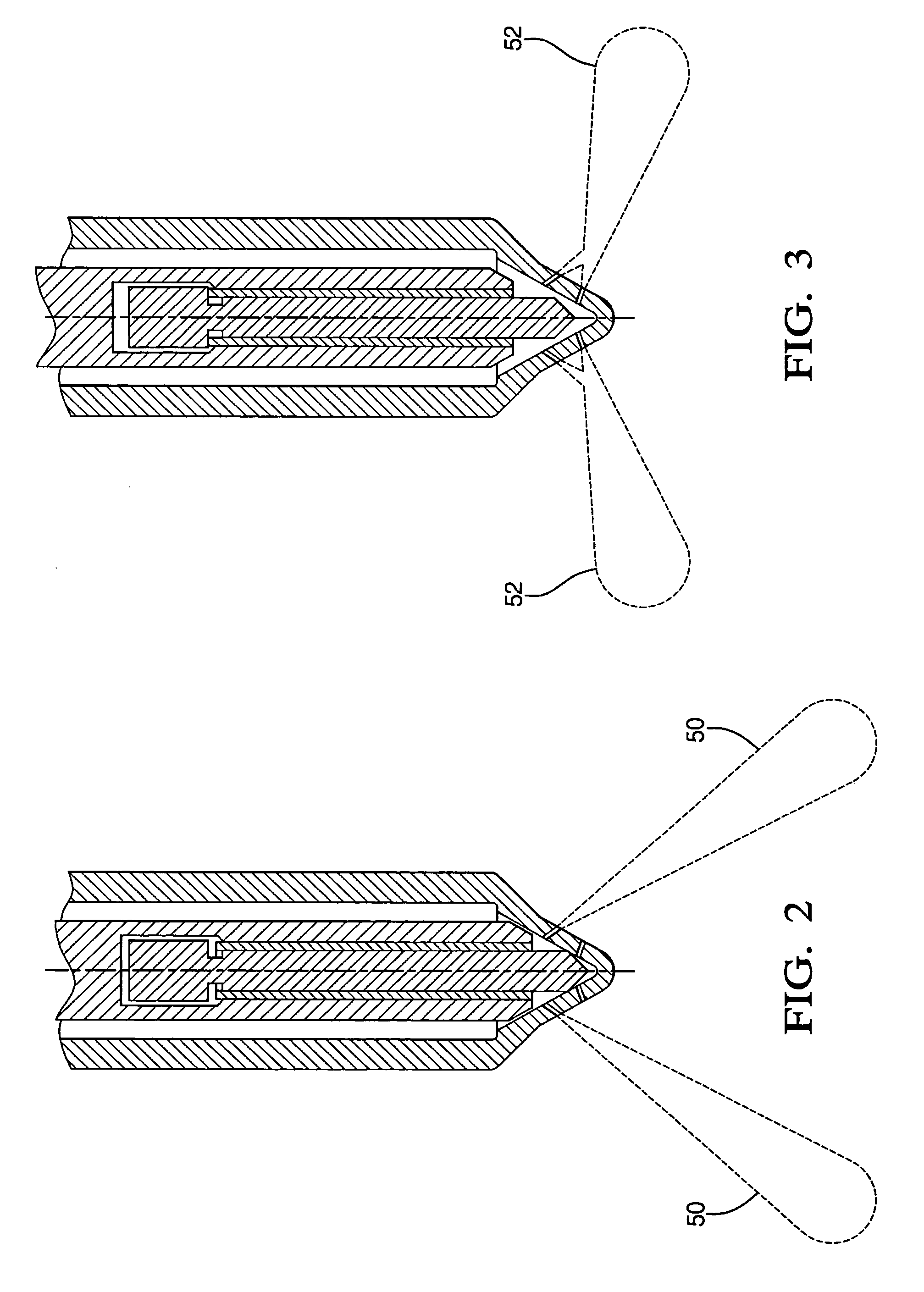
[0025] One exemplary embodiment of the present invention is to provide a fuel injector with a variable area nozzle that produces colliding sprays in one spray position optimized for normal diesel combustion and a non-colliding spray configuration wherein only a smaller set of opening are used for fuel dispersal wherein the spray geometry and flow rate is adapted for other emission technologies such as Homogeneous Charge Compression Ignition (HCCI) or injection of the fuel when the piston is at or near bottom dead center or any other position other than top dead center.

[0026] One in-cylinder emissions reduction technology is to operate the engine in a Homogeneous Charge Compression Ignition (HCCI) mode at light engine loads where exhaust temperatures are too low for effective exhaust catalyst operation and then have the engine operate in a conventional diesel combustion mode for medium to high loads, in conjunction with EGA. HCCI has been demonstrated to deliver very low engine-out ...


PUM


Abstract

A fuel injector nozzle and method for dispersing fuel during a normal combustion operation and a supplemental combustion operation, the fuel injector nozzle comprising: a plurality of first outlet openings configured to disperse fuel in a first arrangement; and a plurality of second outlet openings configured to collide with the fuel passing through the plurality of first openings to disperse fuel in a second arrangement, wherein either the first or second arrangement is selected by the position of the piston.

Description

CROSS REFERENCE TO RELATED APPLICATIONS [0001] This application is a continuation-in-part of U.S. patent application Ser. No. 10 / 819,586 filed: Apr. 7, 2004 the contents of which are incorporated herein by reference thereto.TECHNICAL FIELD [0002] Exemplary embodiments of the present invention are related to an apparatus and method for providing variable spray geometries and flow rates for specific conditions. BACKGROUND [0003] Environmental legislation is driving the exhaust emissions of internal combustion engines down towards zero emissions. To date, diesel engines have largely managed to achieve the present regulatory standards without the aid of exhaust gas after treatment (EGA) however, future standards are intended to drive the use of EGA, wherein emission levels are further reduced. Currently, EGA technologies are being developed, but their installed cost, space claim, reductant requirements, deterioration factors, calibration issues, and other negative aspects continue to ma...

Claims


Application Information

Patent Timeline
Patent Type & Authority Applications(United States)
IPC IPC(8): F02M59/00F02M63/00B05B1/30F02F3/26F02M61/06F02B1/12F02M61/00F02M61/18F02M45/08F02B23/06F02B19/14F02M47/02F02M61/16
CPCF02B1/12F02B19/14F02B23/04F02B23/0669F02B23/0672F02B23/069F02B23/0696F02B2275/14F02D41/3035F02D41/402F02M45/086F02M47/02F02M51/0603F02M61/06F02M61/161F02M61/1813F02M61/182F02M61/1826F02M63/00F02M2200/07F02M2200/46Y02T10/125Y02T10/123Y02T10/12
Inventor DINGLE, PHILIP JG.
Owner DELPHI INT OPERATIONS LUXEMBOURG S A R L
Why Eureka
Try Eureka