Optical sensor

a technology of optical sensors and optical sensors, applied in the field of optical detection systems, can solve problems such as chromatic aberration, inaccurateness, and angle of view aberration, and achieve the effects of accurate measurement, accurate measurement, and accurate measuremen

Inactive Publication Date: 2005-10-13
PANASONIC CORP
View PDF5 Cites 72 Cited by
  • Summary
  • Abstract
  • Description
  • Claims
  • Application Information

AI Technical Summary

Benefits of technology

[0045] Yet another optical detection system according to the present invention includes: a spatial light modulator, which is provided on an optical path of an imaging optical system so as to modulate incoming light; a modulation control section for providing a plurality of modulation patterns for the spatial light modulator; a photodetector having a plurality of photosensitive areas to receive the incoming light that has been modulated by the spatial light modulator; and a photosensor selecting section for selecting one of the photosensitive areas to receiv

Problems solved by technology

However, such approximation is accurate enough only within a relatively narrow range near the optical axis.
Accordingly, in actually handling a rather big image, an aberration associated with an angle of view is a problem.
Also, in treating multiple wavelengths as in a color image, a chromatic aberration is a problem.
However, to minimize the aberration associated with the angle of view and the chromatic aberration over the entire area of a photodetector, the compound lens needs to consist of a lot of lenses, which increases the overall cost of the required members, the assembling and adjustment costs, and the size of the optical instrument, too.
However, the aberrations resulting from the angle of view and the difference in wavelength would rather increase by doing just that.
Nevertheless, if the number of lenses to make up the compound lens were increased to avoid that situation, then the optical instrument would get too much complicated or bulky.
As can be seen, reduction of the aberrations and simplification of the optical system are contradictory purposes, which are hard to achieve at the same time and are still key issues in optics design of today.
Also, in a zoom lens optical system, for example, the aberrations must be reduced with the magnification of imaging changed, thus making it even more difficult to simplify and downsize the optical system.
Furthermore, not just the lens system but also a light quantity control mechanism such as a diaphragm and a shutter increase the size of an optical instrument.
However, depending on the angle of incidence of a bundle of rays entering a lens, the bundle of rays may pass just a portion of each lens, thus making it difficult to design and arrange the optical elements so as to adjust the light quantity uniformly over the entire area of the photodetector.
The presence of such a light quantity control mechanism and the constraints on its arrangement constitute another obstacle to simplifying and downsizing the optical system.
Firstly, only a few types of aberrations can be corrected and reduction of the aberrations over the entire area of the photodetector and simplification of the optical system are hard to realize at the same time.
Document No. 1 does disclose a configuration that can be used effectively to correct the focal point shifting and image distortion but does not disclose any configuration for reducing aberrations of differen

Method used


Image

  • Optical sensor
  • Optical sensor
  • Optical sensor

Examples


embodiment 1

[0055] Hereinafter, an optical detection system according to a first preferred embodiment of the present invention will be described with reference to FIGS. 1 through 6.

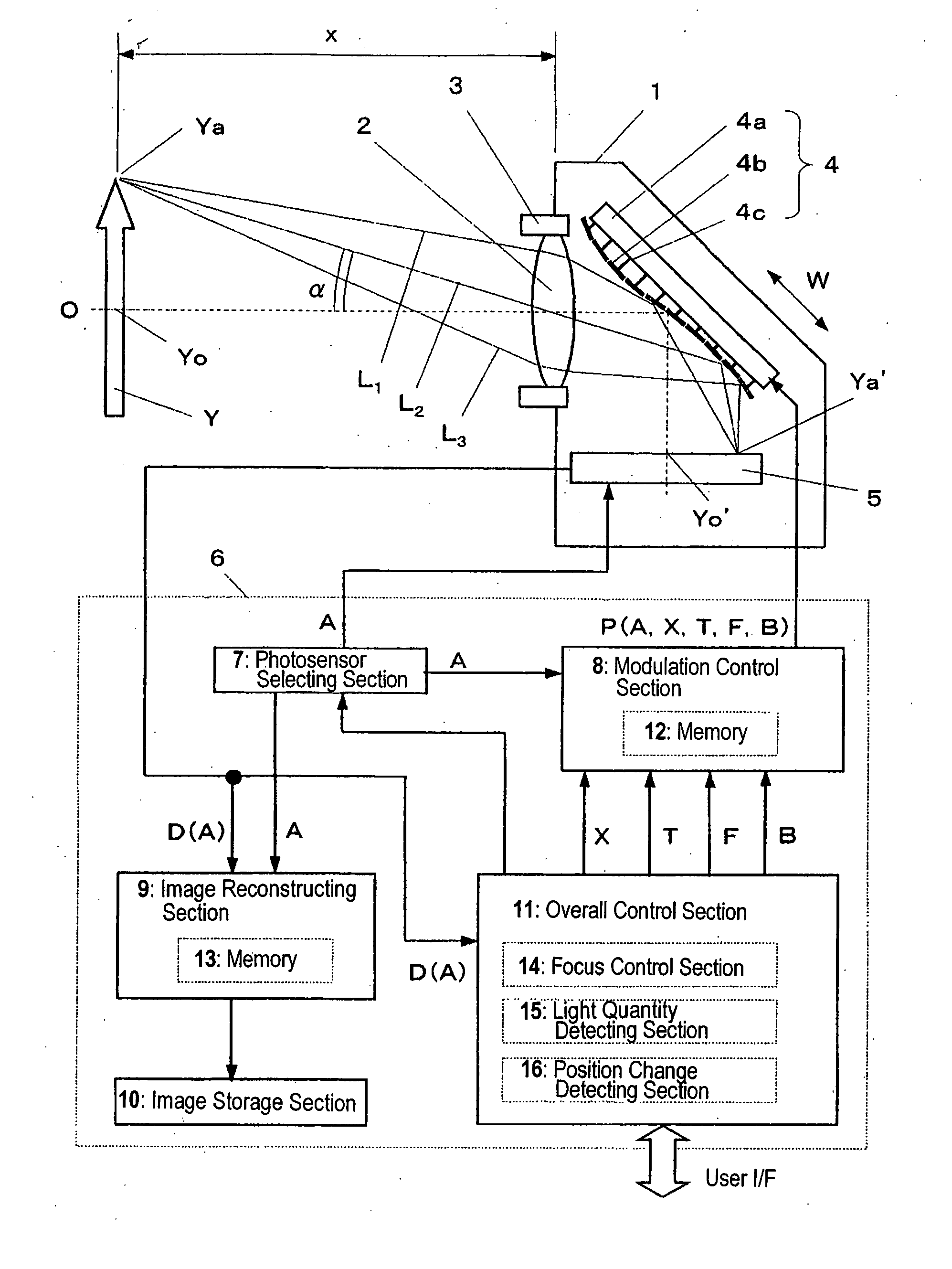
[0056] First, referring to FIG. 1, illustrated is a schematic configuration for an optical detection system according to this preferred embodiment. In the housing 1 of the optical detection system shown in FIG. 1, a lens 2, a lens moving mechanism 3, a deformable mirror 4, a photodetector 5, and a controller 6 are provided. As shown as a block diagram in FIG. 1, the controller 6 includes a photosensor selecting section 7, a modulation control section 8, an image reconstructing section 9, an image storage section 10 and an overall control section 11.

[0057] The lens 2 is an objective lens for condensing the light that has come from an object Y, which is the target to be imaged. After having passed through the lens 2, the incoming light has its phase modulated by the deformable mirror 4 functioning as a spatial light ...

embodiment 2

[0115] Hereinafter, an optical detection system according to a second preferred embodiment of the present invention will be described with reference to FIG. 7, which illustrates a schematic configuration for an optical detection system according to the second preferred embodiment of the present invention.

[0116] In this preferred embodiment, the deformable mirror 4, a photodetector 55, and a controller 56 are fixed to the housing 51 of the optical detection system. The controller 56 includes a modulation control section 57, the image storage section 10 and an overall control section 58. Also, a replaceable lens unit 52 is mounted on the housing 51. The deformable mirror 4 and image storage section 10 have the same configurations as those already described for the first preferred embodiment.

[0117] The lens unit 52 is provided so as to be attachable to, and removable from, the housing 51 and to be replaceable with another lens unit. In this preferred embodiment, the lens unit 52 incl...

embodiment 3

[0136] Hereinafter, an optical detection system according to a third preferred embodiment of the present invention will be described with reference to FIG. 8. In this preferred embodiment, portions of the spatial light modulator and photosensor selecting section are implemented as a liquid crystal element and the photodetector is implemented as a photosensitive film. FIG. 8 illustrates a schematic configuration for an optical detection system according to the third preferred embodiment of the present invention.

[0137] In this preferred embodiment, the lens 2, the lens moving mechanism 3, a liquid crystal phase modulator 72, a liquid crystal shutter 73, a photosensitive film 74 and a controller 75 are fixed to the housing 71 of the optical detection system. The controller 75 includes a photosensing selector 76, a modulation control section 77, and an overall control section 78. The lens 2 and lens moving mechanism 3 have the same configurations as those already described for the firs...


PUM


Abstract

An optical detection system according to the present invention includes: a spatial light modulator for modulating the phase of incoming light; a photodetector having a plurality of photosensitive areas to receive the light of which the phase has been modulated by the spatial light modulator; a photosensor selecting section for selecting at least one of the photosensitive areas and activating the selected photosensitive area effectively; and a modulation control section for providing a modulation pattern, associated with the photosensitive area that has been selected by the photosensor selecting section, for the spatial light modulator.

Description

TECHNICAL FIELD [0001] The present invention relates to an optical detection system including a spatial light modulator and more particularly relates to an optical detection system having the function of controlling an image being formed on its photodetector. BACKGROUND ART [0002] Generally speaking, a compound lens, consisting of any number of lenses in any of various combinations (e.g., seven lenses in six groups or eleven lenses in ten groups), is often used in an imaging optical system such as a camera. According to a paraxial theory, such a compound lens is equivalent to a single convex lens. However, such approximation is accurate enough only within a relatively narrow range near the optical axis. Accordingly, in actually handling a rather big image, an aberration associated with an angle of view is a problem. Also, in treating multiple wavelengths as in a color image, a chromatic aberration is a problem. [0003] To reduce such aberrations, various combinations of refractive in...

Claims


Application Information

Patent Timeline
IPC IPC(8): H04N3/08H04N5/225
CPCG02B26/06H04N3/08H04N5/2259H04N5/772H04N5/907H04N9/8042H04N23/58
Inventor MUSHIKA, YOSHIHIRO
Owner PANASONIC CORP
Why Eureka
Try Eureka