Microelectromechanical structures, devices including the structures, and methods of forming and tuning same

a micro-electromechanical and structure technology, applied in the direction of micro-structural devices, micro-structural technology, relays, etc., can solve the problems of significant variation in mass and stiffness of mechanical structures, altering the vibrating mass, and difficult to manufacture well-defined resonance frequencies. achieve the effect of improving micro-electromechanical structures and devices

Inactive Publication Date: 2005-10-13
AXON TECH
View PDF1 Cites 40 Cited by
  • Summary
  • Abstract
  • Description
  • Claims
  • Application Information

AI Technical Summary

Benefits of technology

This patent describes better ways for making small machines with moving parts called MEMS (short for micromachines). These improvements involve adding or removing material from around the part that moves to change its behavior. By doing this, researchers hope they will create more precise and reliable MEMS devices.

Problems solved by technology

This patent discusses how challenging it is to make sure that microdevices made through various processes have consistent properties and work properly. These issues affect things like accelerometers, vibrators, and even lasers. To solve this problem, researchers want better ways to control these devices after they're done being made.

Method used


Image

  • Microelectromechanical structures, devices including the structures, and methods of forming and tuning same
  • Microelectromechanical structures, devices including the structures, and methods of forming and tuning same
  • Microelectromechanical structures, devices including the structures, and methods of forming and tuning same

Examples


Embodiment Construction

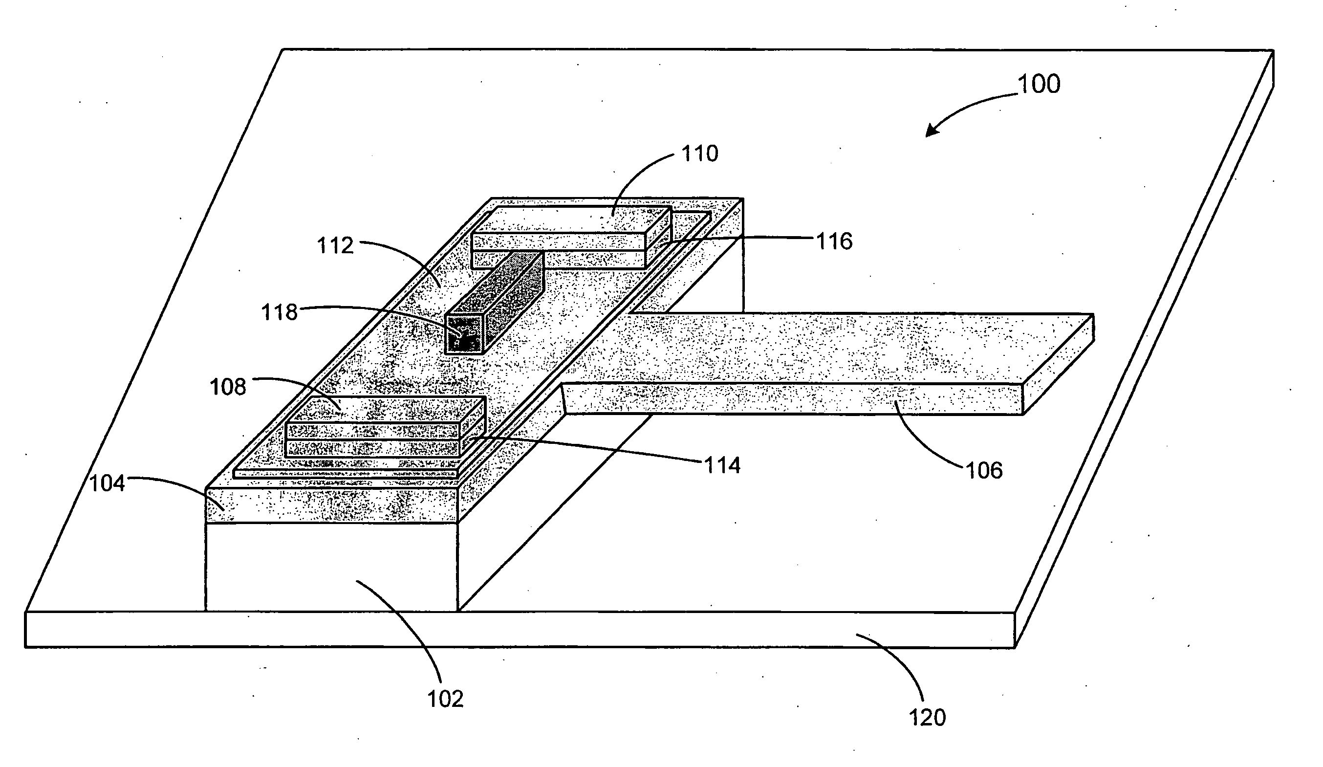
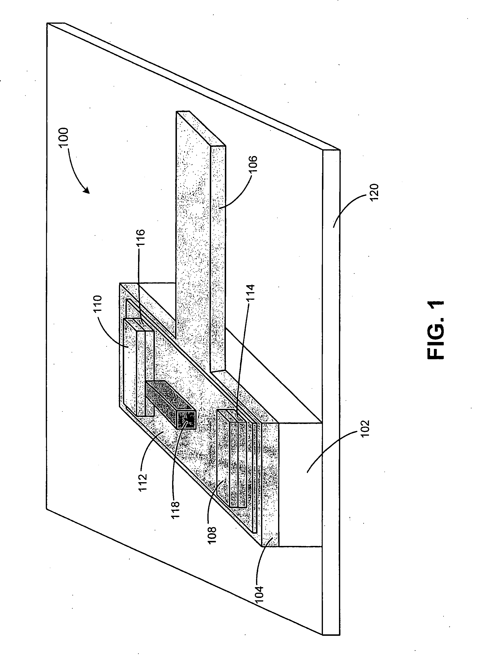
[0018]FIG. 1 illustrates a microelectromechanical device 100 formed on a surface of a substrate 120 in accordance with an exemplary embodiment of the present invention. Device 100 includes a support 102, a base 104, a mechanical element 106, electrodes 108 and 110, an ion conductor 112, and optionally includes buffer or barrier layers 114 and 116. As will be discussed in greater detail below, device 100 can be used to form devices such resonators and the like. Device 100 is advantageous compared to conventional microelectromechanical devices because, among other reasons, device 100 can be tuned or manipulated by altering an amount of mass on base 104 proximate element 106. By altering a mass distribution on base 104, stress fields in element 106 can be manipulated, and thus a resonant frequency of the device can be altered. In this manner, a resonant frequency of device 100 can be altered, while maintaining the high Q factor of the device.

[0019] During a tuning operation, mechanica...


PUM


Abstract

A microelectromechanical structure and device and methods of forming and using the structure and device are disclosed. The structure includes a mechanical element, an ion conductor and a plurality of electrodes. Mechanical properties of the structure are altered by applying a bias across the electrodes. Such structures can be used to form devices such as resonators for RF applications.

Description


Claims


Application Information

Patent Timeline
Owner AXON TECH
Why Eureka
Try Eureka