
System and method for analyzing a network and/or generating the topology of a network

a network and topology technology, applied in the field of system and method for generating the topology of a network, can solve the problem of determining the topology of such a network, and achieve the effect of simplifying and automating the analysis and representation of the topology

Inactive Publication Date: 2005-10-13
SIEMENS AG
View PDF18 Cites 19 Cited by
  • Summary
  • Abstract
  • Description
  • Claims
  • Application Information

AI Technical Summary

Benefits of technology

[0004] The object of the present invention is to simplify and automate the analysis and representation of the topology of any arbitrary network for the exchange of data, so that the need for human assistance can be obviated.

Problems solved by technology

Until now it has only been possible to determine the topology of such a network manually, i.e. by a person and / or by calling on the assistance of very time-consuming iterative methods.

Method used


Image

  • System and method for analyzing a network and/or generating the topology of a network
  • System and method for analyzing a network and/or generating the topology of a network
  • System and method for analyzing a network and/or generating the topology of a network

Examples


Embodiment Construction

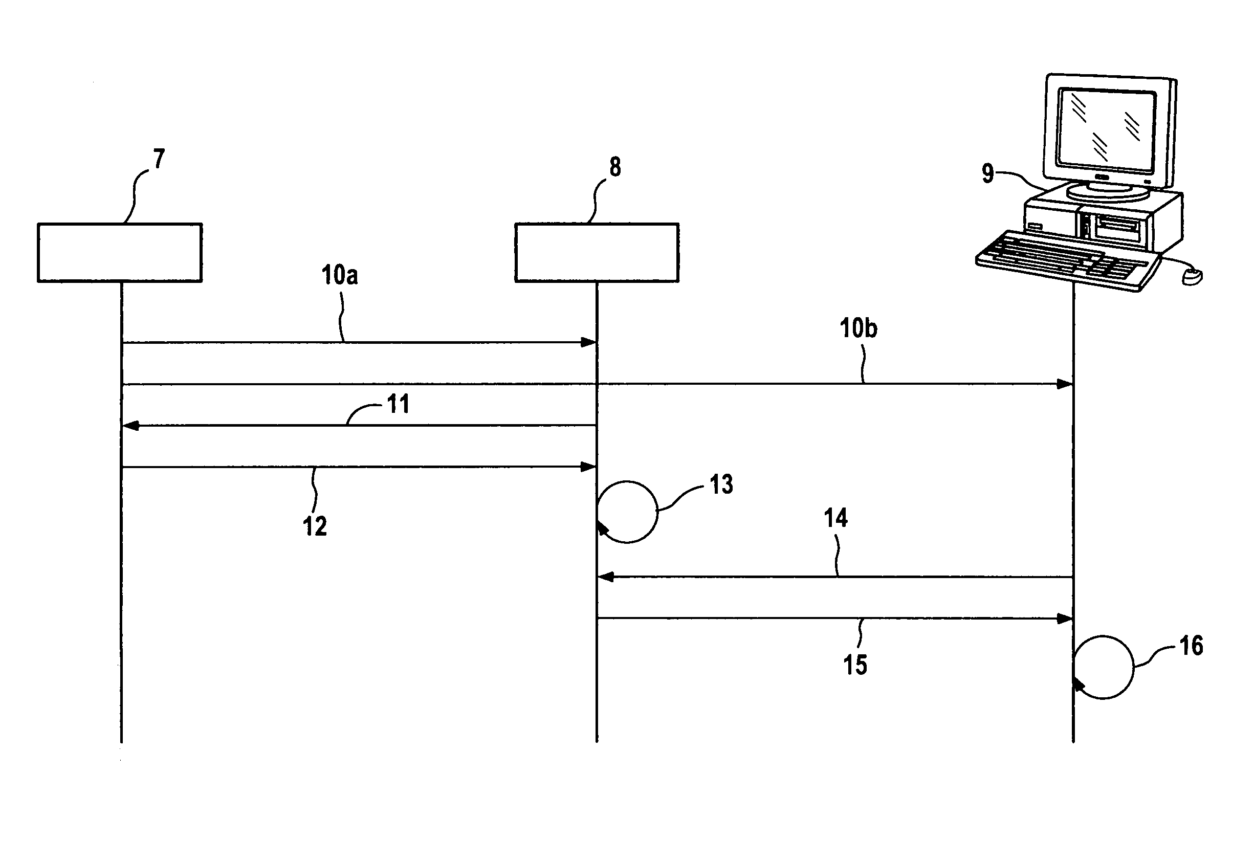
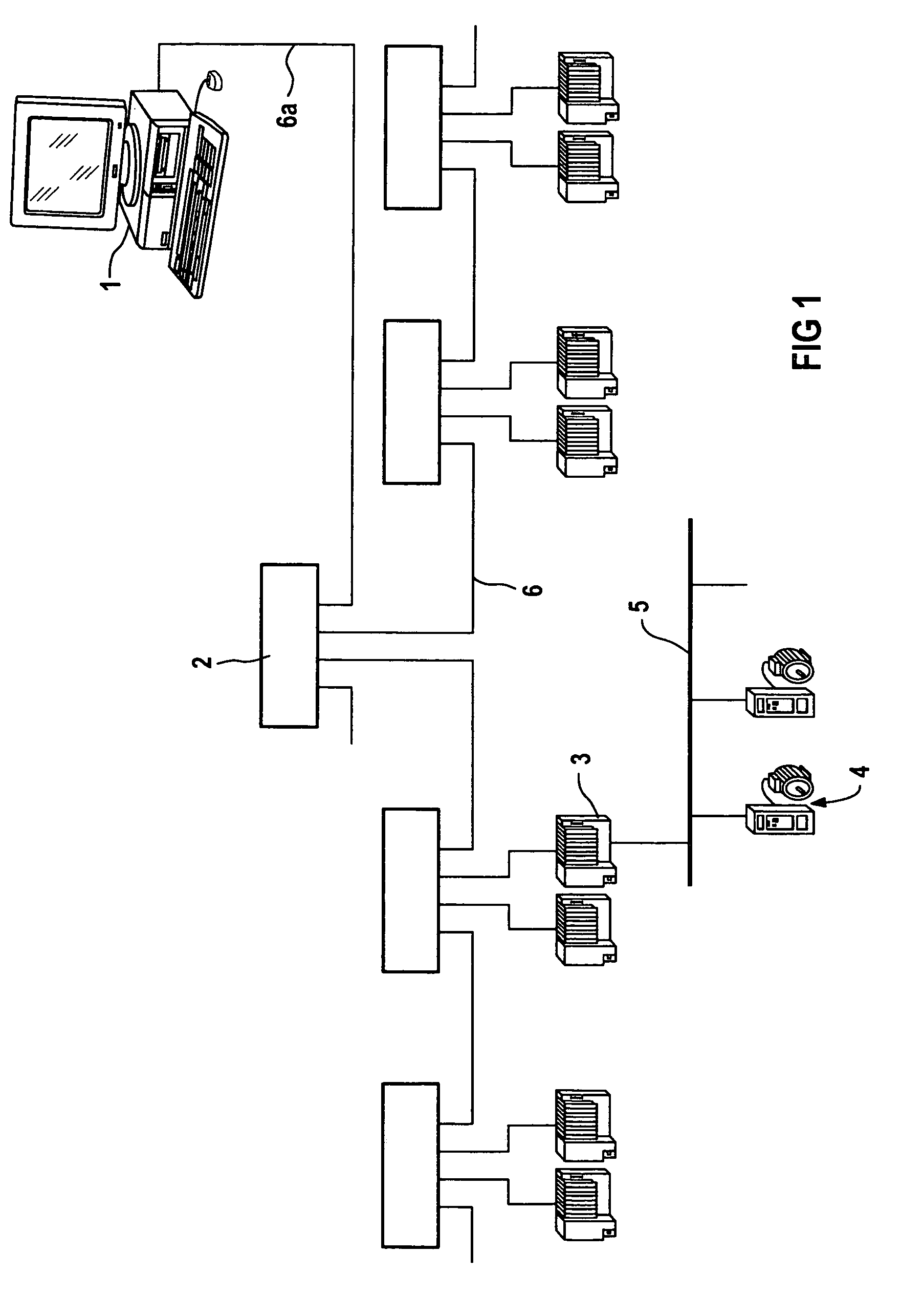
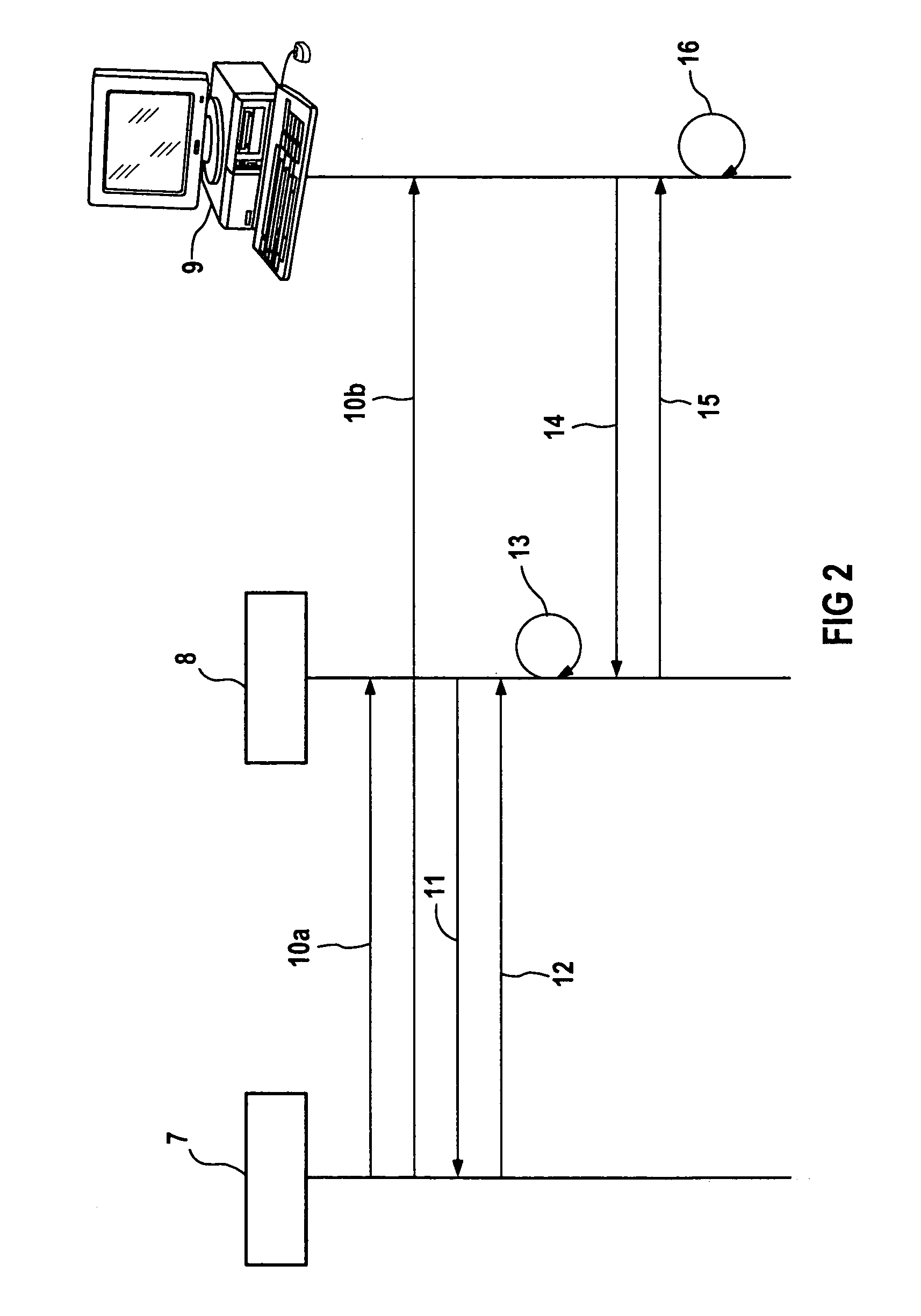
[0019] The schematic representation as in FIG. 1 shows a first form of embodiment for a network, for example a switched Ethernet with several elements. Further examples of such networks are: Fieldbus, Profibus, Ethernet, Fast Ethernet, Industrial Ethernet or Fire-Wire, but also clocked data networks such as the Isochronous Real-time Ethernet, for example, and combinations of them. The networks used can either be equipped or not with real-time characteristics, such as clock synchronization and equidistance. In FIG. 1, for example, several coupling elements, also referred to as switches, of which for the sake of presentational clarity only Switch 2 is shown, can be linked with each other over data lines, of which for the sake of presentational clarity only the data lines 6 and 6a are shown. Thus such data lines are used to connect the switches to nodes, for example industrial computers, PCs or other computers, etc., of which for the sake of clarity only node 3 is shown. The nodes can ...


PUM


Abstract

The invention relates to a system and method called autotopology of a network or advertising based network management which enables the analysis and automatic graphical and hierarchical representation of any hierarchical or flat network topology, especially a switched Ethernet (SE). The autotopology can be used for self-configured networks (for example by using zeroconf) and for any otherwise configured networks, especially using DHCP or manually configured networks. The use of zeroconf is called autoconfiguration. Autoconfiguration and autotopology enable a comfortable and safe administration of a network. Administration of a self-configured network using the autotopology data proceeds in a separate and low-priority sub-network (link local) so that the productive operation of the network remains undisturbed. The topology of the network is used as a clear possibility of administering a network. Administration of the network is possible immediately after determination of the topology.

Description

CROSS REFERENCE TO RELATED APPLICATIONS [0001] This application is the U.S. National Stage of International Application No. PCT / DE03 / 00199, filed Jan. 24, 2003 and claims the benefit thereof. The International Application claims the benefits of German application No. 10204826.6 filed Feb. 6, 2002, both of the applications are incorporated by reference herein in their entirety.FIELD OF INVENTION [0002] The invention relates to a system and method for analyzing a network and / or generating the topology of a network. BACKGROUND OF INVENTION [0003] With networks, the elements in the network generally have a unique network address for the purpose of exchanging data, by means of which it is possible to exchange data selectively. This situation enables the elements in the network, for example switches, computers, etc., to make themselves known by sending their network address to all the other elements in the network. Until now it has only been possible to determine the topology of such a ne...

Claims


Application Information

Patent Timeline
Patent Type & Authority Applications(United States)
IPC IPC(8): H04L12/24
CPCH04L41/0266H04L41/26H04L41/22H04L41/12
Inventor BRAUN, JOSEFFELD, JOACHIMROTH, STEFANTALANIS, THOMASTROSTER, THOMASVOLKMANN, FRANK
Owner SIEMENS AG
Learn More