Ray-by-ray fourier image reconstruction from projections

a fourier image and projection technology, applied in the field of raybyray fourier image reconstruction from projections, can solve the problems of increasing the difficulty of reconstruction algorithms, the use of more complex reconstruction methods, and the inability to produce images with unacceptable artifacts

Inactive Publication Date: 2005-10-13
HINSHAW WALDO S
View PDF1 Cites 6 Cited by
  • Summary
  • Abstract
  • Description
  • Claims
  • Application Information

AI Technical Summary

Benefits of technology

[0030] The RbR method has the feature that the data from each source location can be processed and loaded into F-space as soon as it is available without waiting for all of the data to b

Problems solved by technology

Since the rays are no longer parallel, more complex reconstruction methods have to be used.
Other algorithms have been proposed but are too complex fo

Method used


Image

  • Ray-by-ray fourier image reconstruction from projections
  • Ray-by-ray fourier image reconstruction from projections
  • Ray-by-ray fourier image reconstruction from projections

Examples


Embodiment Construction

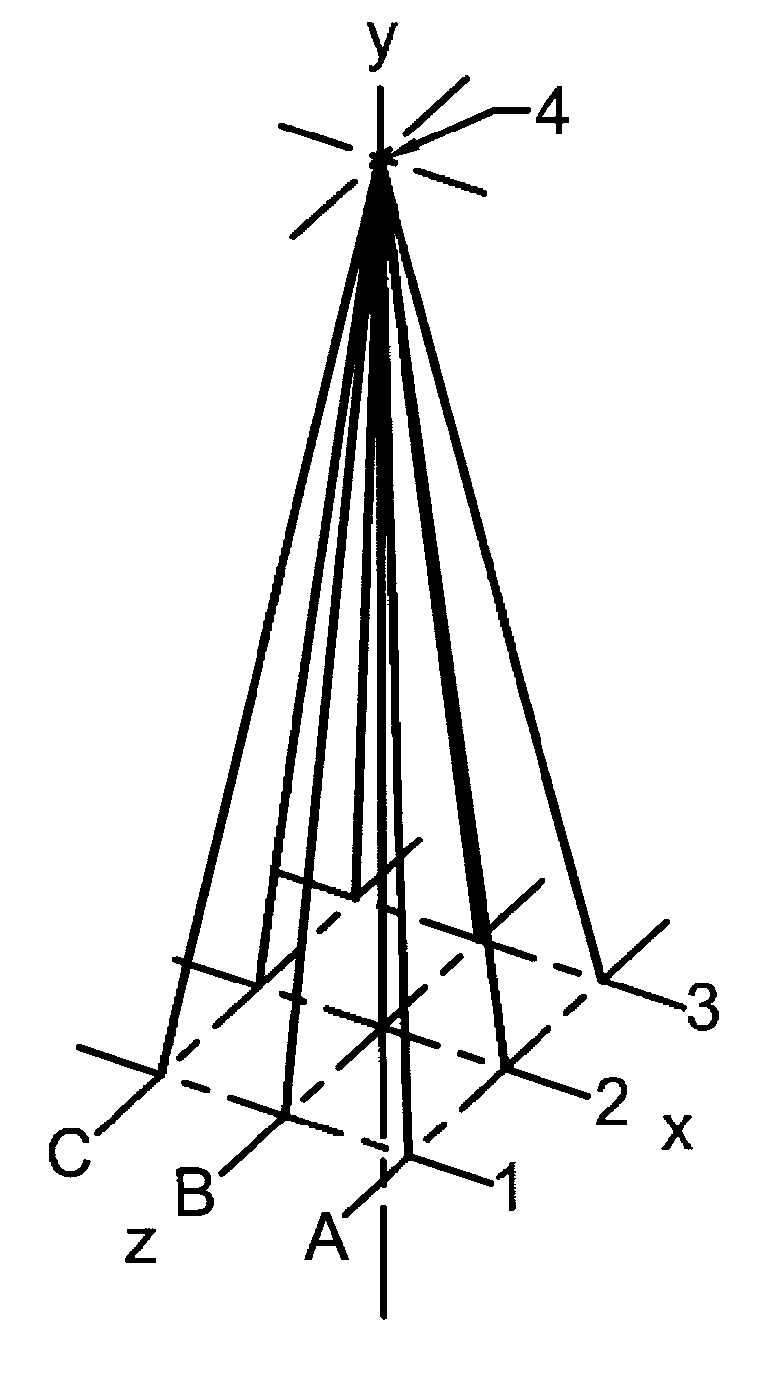
[0035] The RbR method can be applied equally well to a wide range of imaging technologies and, in particular, to any of the several ways in which cone-beams are used in CT, including helical scanning and tomosynthesis. The following embodiment shows how to apply the invention to one specific geometry that incorporates x-rays and cone-beam geometry. The following geometry has a fixed cylinder of detector elements and a single rotating source that provides a cone-beam of x-rays. The geometry will be described with reference to the drawings.

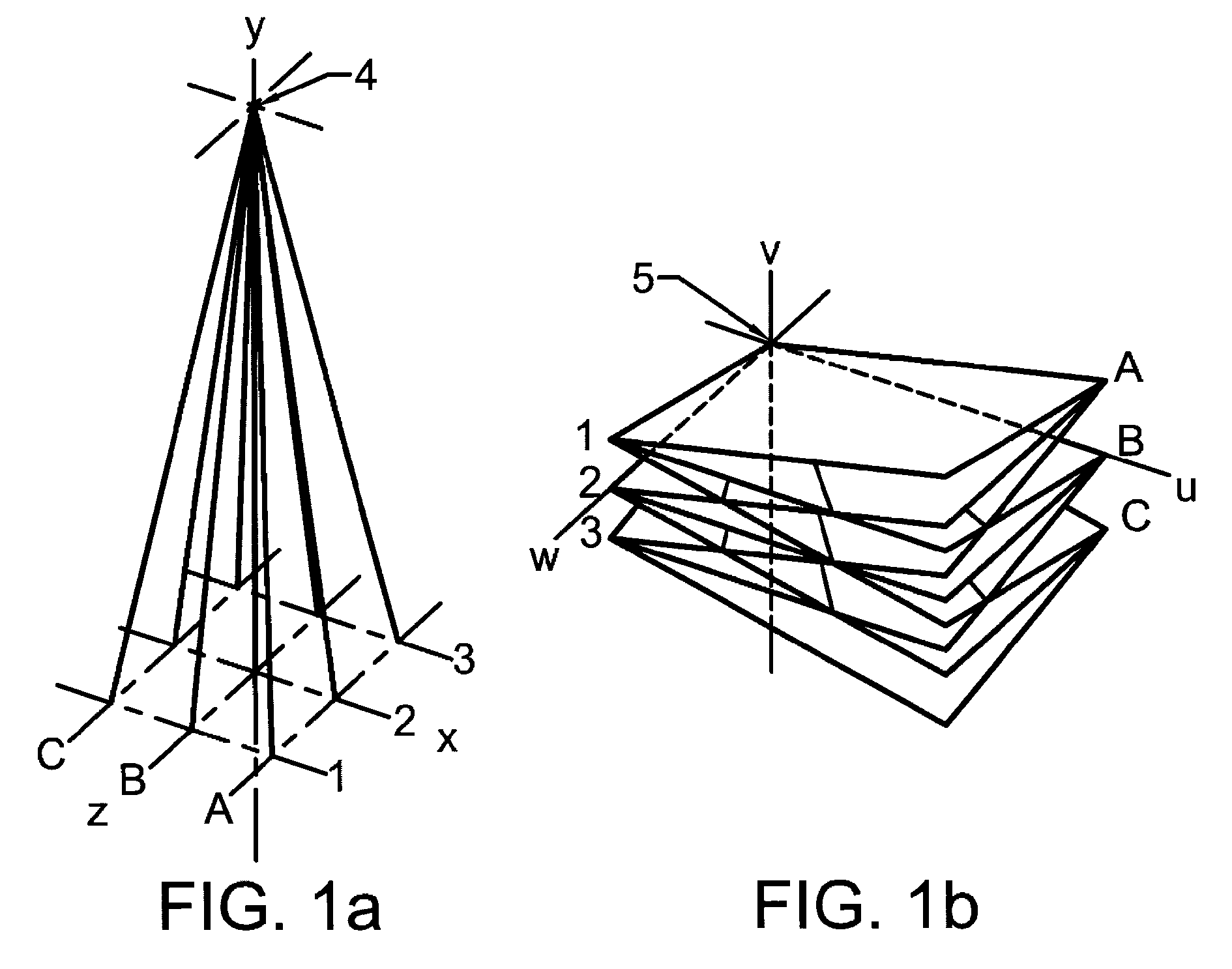
[0036]FIG. 1a shows a very simple cone-beam consisting of nine rays arranged in three rows 1, 2, 3 parallel to the x-axis and three columns A, B, C parallel to the z-axis. The three rays in row 2 are on the x-axis and the three rays in column B are on the z-axis. The source 4 and the ray at the intersection of row 2 and column B, or ray 2B, are both on the z-axis. FIG. 1b shows the nine corresponding F-component planes in F-space. For example, the ...


PUM


Abstract

Two-dimensional or three-dimensional images of the distribution of a property of an object are formed by passing rays of radiation through the object and detecting how much each ray is attenuated. The Fourier transform is taken of each individual ray but only the zeroth term of the transform along the path of the ray is retained. Each of these transforms is added into a two or thee-dimensional array. If the three-dimensional distribution is being imaged, the transform is a plane of numbers, which is added into the three-dimensional array at right angles to the path of the ray. The numbers in the array are corrected for the non-uniform density of data. After enough such rays in enough different directions are applied, the distribution of the property is obtained by taking the inverse Fourier transform of the data in the array.

Description

BACKGROUND OF INVENTION [0001] During the last few decades, methods have been developed for reconstructing the spatial distribution of an internal property of an object by acquiring multiple projections of that property and then combining them using a reconstruction algorithm. Although there are various applications of these methods, the medical imaging system using x-rays and computed tomography, the CT scanner, is perhaps the best known. The CT scanner typically obtains the distribution of attenuation in a two-dimensional slice of the object by taking projections through 180 degrees around the slice. However, reconstruction methods also can work in three dimensions. For a three-dimensional reconstruction, projections would be taken over a hemisphere. [0002] The earliest and most often used CT algorithm is commonly known as filtered back projection, or simply FBP. A set of parallel x-rays is sent through a selected slice of the object in the plane of the slice and in a given direct...

Claims


Application Information

Patent Timeline
IPC IPC(8): A61B6/00A61B6/03G01N23/00G21K1/12H05G1/60
CPCY10S378/901G06T11/003
Inventor HINSHAW, WALDO S.
Owner HINSHAW WALDO S
Why Eureka
Try Eureka