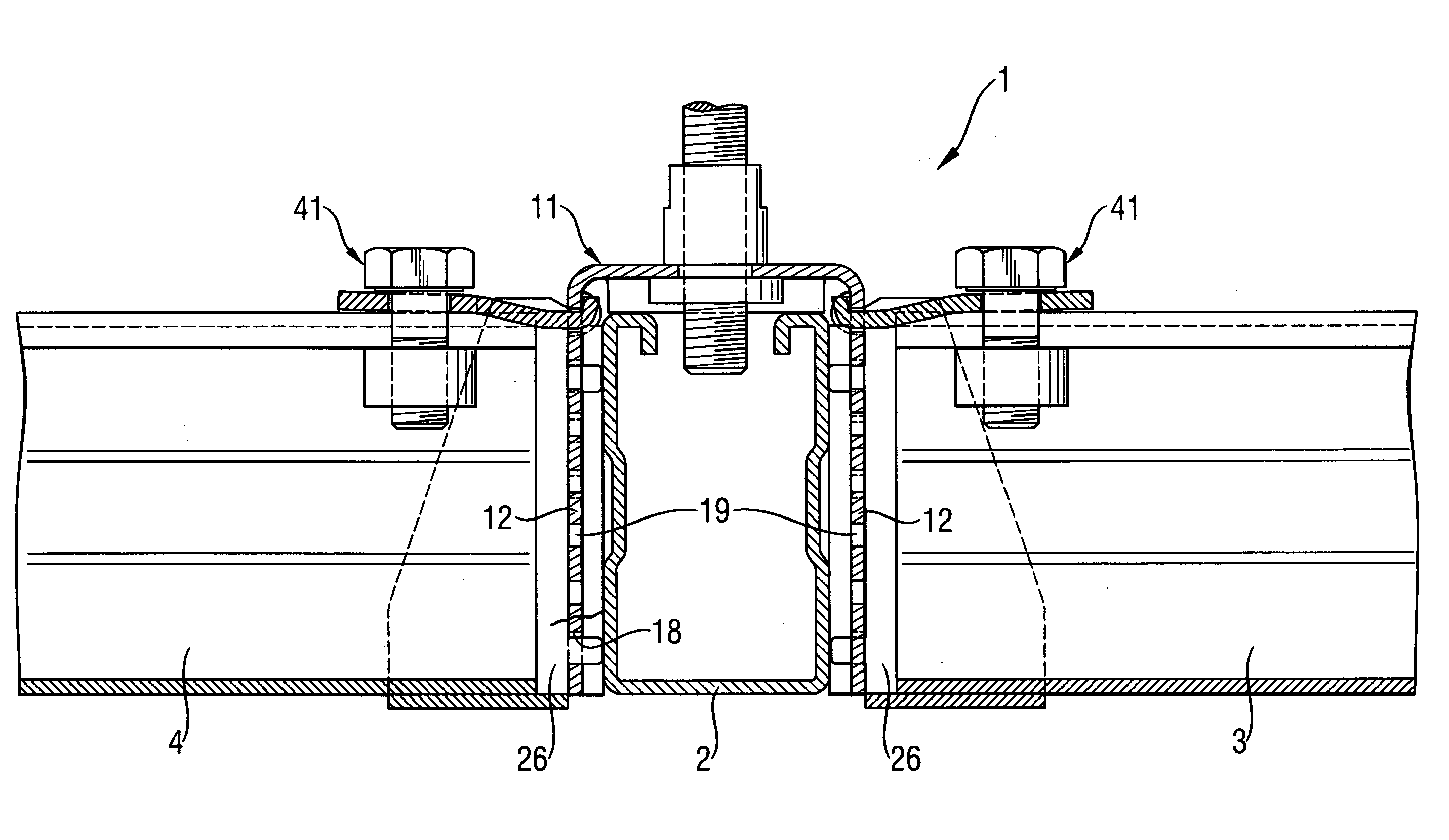
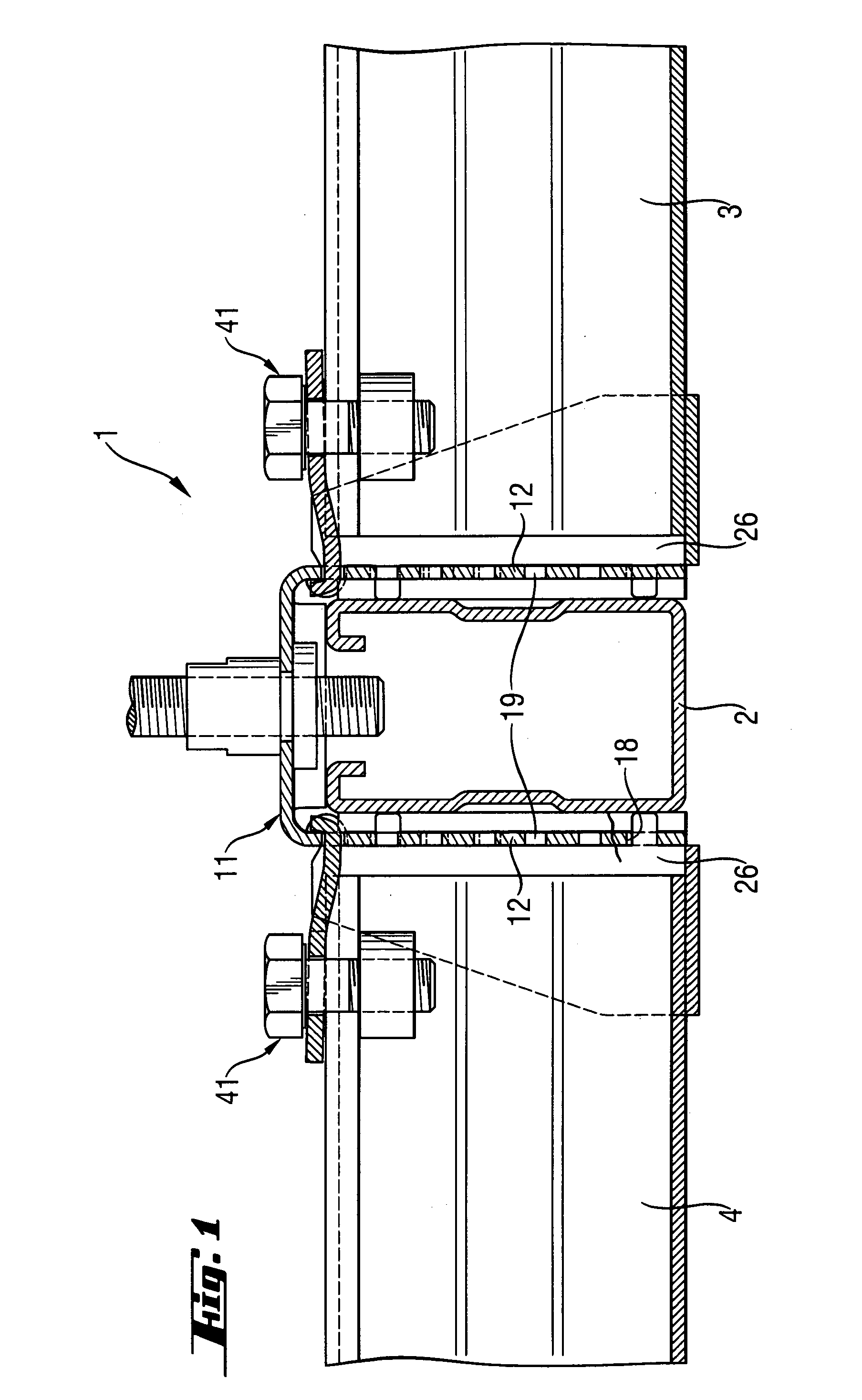
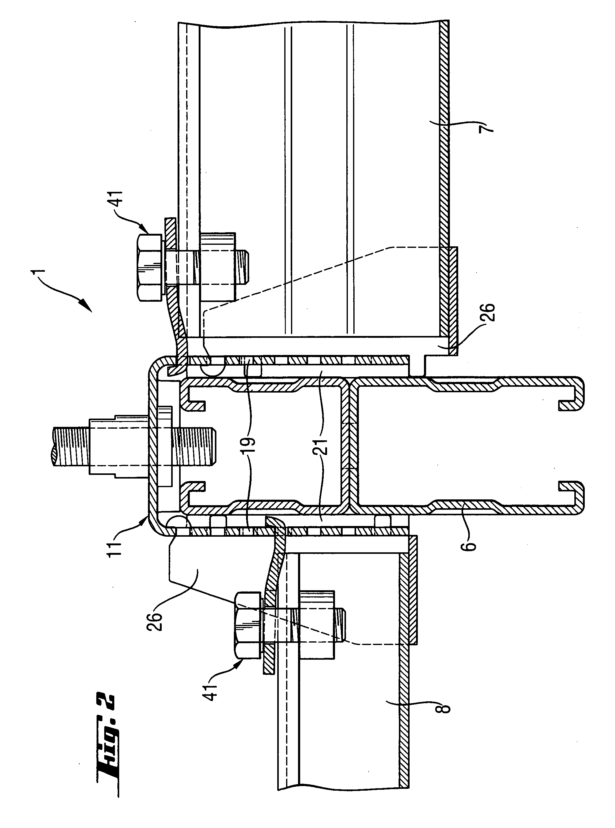
[0018] In order to improve the flexibility of the inventive connection device, the spaced from each other and located opposite each other elementary receptacles are arranged on both legs of the intermediate member at different distances from the connection section of the intermediate member for receiving two receiving members. The elementary receptacles on both legs have advantageously the same profile. The receiving members can be set in both legs of the intermediate member at the same distance from the connection section or at different distances from the connection section. This arrangement of the inventive connection device permits to arrange two opposite mounting rails on the first mounting rail, e.g., to form a grid ceiling. In the receiving members, there can be introduced mounting rails having the same height or different heights.
[0020] Advantageously, the setting-in elements are arranged on the edges of the legs of the receiving member and in planes formed by the legs. This arrangement of the setting-in elements provides for a simple and cost-effective manufacturing of the receiving member by a
stamping and bending process. Further, with this construction of the receiving member, no material sections are formed which would reduce at least partially the receiving space formed by planes of the legs of the receiving member. This noticeably facilitates the
assembly of the connection device and the connection of the further mounting rails with the first mounting rail.
[0021] Advantageously, a plurality of engagement elements are provided on the legs of the at least one receiving member for providing a locking connection between the at least one receiving member and the intermediate member. Preferably, the engagement elements are formed as pin-shaped elements and are provided on the edges of the legs of the at least one receiving member. The engagement elements are so arranged relative to each other and relative to the setting-in elements on the legs of the receiving member and are arranged opposite each other in such a way that they can be inserted in the elementary receptacles, which are provided for the setting-in elements on the at least one leg of the intermediate member, for forming a locking connection. When, e.g., the receiving member is mounted in lower elementary receptacles of the intermediate member, the engagement elements can be located outside of the free end of the leg of the intermediate member remote from the connection section of the intermediate member. The pin-shaped elements can be formed as cylindrical or square pin elements. In addition, the engagement elements can be formed, in a direction from their free ends, as trapezoidal or conical elements, which facilitate, in particularly upon setting the receiving member in the intermediate member, penetration of the engagement elements in the elementary receptacles of the legs of the intermediate member.
[0026] Advantageously, the setting-in section has a smaller width than the bearing section. The width of the setting-in section corresponds maximum to the distance between the legs of the receiving member. For reducing the consumption of material during manufacturing of the securing element, preferably, the width of the setting-in section corresponds to the width of the securing receptacles in the leg of the intermediate member. The width of the bearing section corresponds substantially to the total width of the mounting rail.
[0027] Advantageously, the setting-in section extends to a plane, which is defined by the bearing section, at an angle α from 0° to 25°, preferably, at an angle α from 5° to 15°. However, the setting-in section of the securing element can lie, viewing from the free end of the hook-shaped section when the setting-in section has a hook shape, in the same plane as the bearing section. The through-opening for the fastening means, which secures the mounting rail to the connection device is formed, preferably, in the bearing section. With the angular arrangement of the setting-in section relative to the bearing section, an additional tightening force acts on the connection between the mounting rail and the connection device upon tightening of the fastening means. Thereby, the reliability of the connection is increased. The securing element permits to compensate the manufacturing tolerances of the connection device and also the tolerances of the connection between the connection device and the mounting rail.

