Implantable medical device with optimized shape

a medical device and shape technology, applied in the field of medical devices, can solve the problems of inability to design implantable prosthetic devices, inability to respond to implantable devices for treating venous valve insufficiency, and insufficient responsiveness of implantable devices

Active Publication Date: 2005-10-13
COOK MEDICAL TECH LLC
View PDF99 Cites 220 Cited by
  • Summary
  • Abstract
  • Description
  • Claims
  • Application Information

AI Technical Summary

Benefits of technology

[0009] In one embodiment, a frame can expand from a compressed, or unexpanded, delivery configuration to one or more radially expanded deployment configurations, for example through self-expansion or balloon expansion of the frame. The expanded configuration can have any suitable cross-sectional configuration, including circular or elliptical. In one embodiment, the frame can be oriented along the longitudinal axis of a body vessel in the expanded or compressed configurations. In certain embodiments, the frame in its expanded or compressed configurations can be moveable from or to a configuration having a circular cross-section and a configuration having an elliptical cross-section. In one embodiment, the expanded configuration is itself readily moveable between a circular tubular configuration and elliptical tubular configuration, for example in response to conformational changes in the interior wall of a vein or other body vessel.

Problems solved by technology

Frequently, fluid flows in a substantially unidirectional manner along the length of the vessel.
Dynamic fluctuations in the shape of the lumen of a vein pose challenges to the design of implantable prosthetic devices that conform to the interior shape of the lumen of a vein.
Therefore, the shape of a lumen of a vein, which is substantially elliptical in cross-section, can undergo dramatic dynamic change as a result of varying blood flow velocities and volumes therethrough, presenting challenges for designing implantable intraluminal prosthetic devices that more closely conform to the changing shape of the vein lumen.
Implantable devices for treating venous valve insufficiency are often not designed to be responsive to dynamic changes in the shape of a body vessel lumen, such as in a vein.
Similarly, implantable device configurations can be unresponsive to dynamic changes of the vessel cross-section, and can locally distort the shape of the body vessel.

Method used


Image

  • Implantable medical device with optimized shape
  • Implantable medical device with optimized shape
  • Implantable medical device with optimized shape

Examples


first embodiment

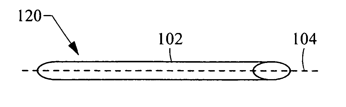
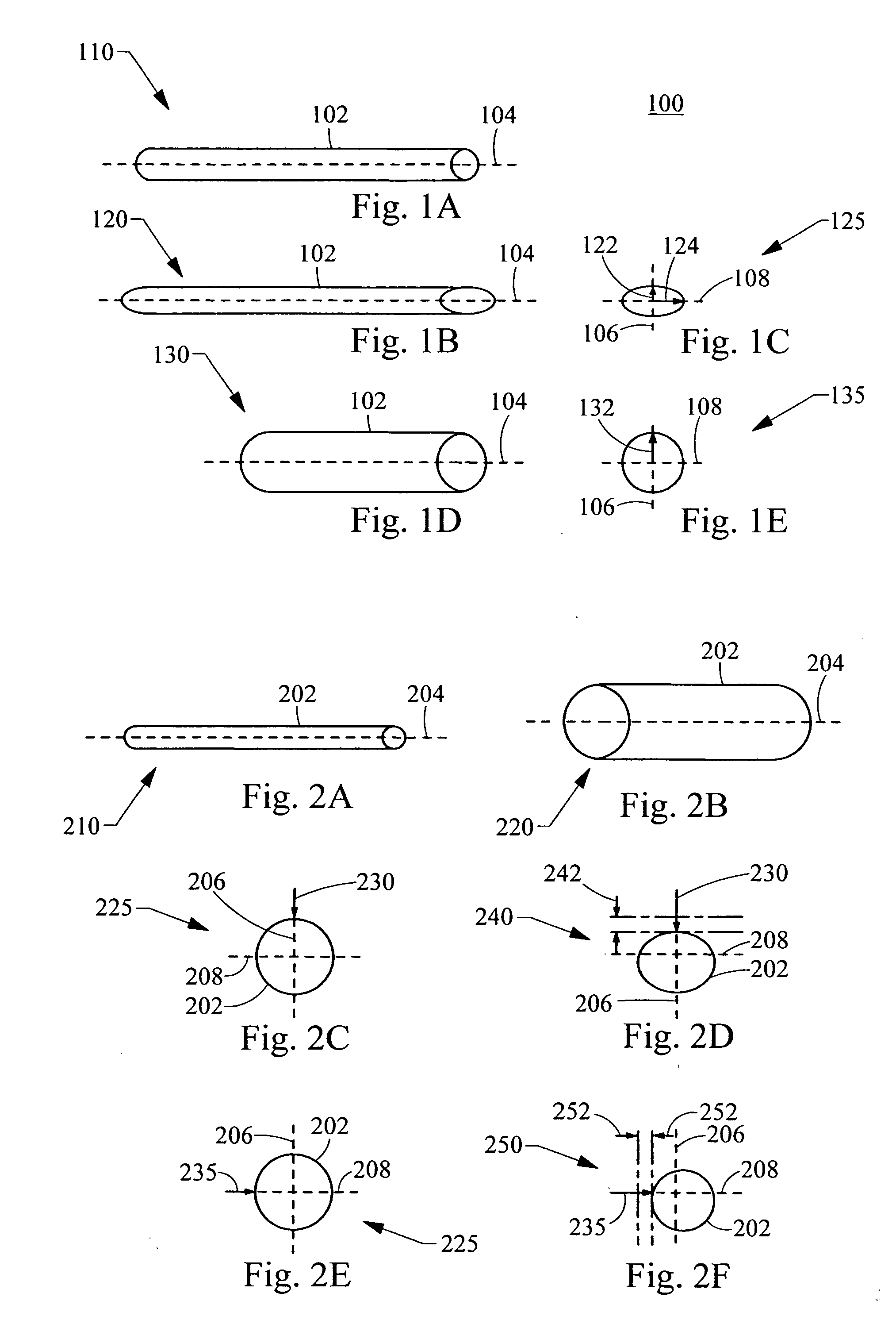
[0038]FIG. 1A is a perspective view of a medical device 100 according to the invention. The medical device comprises a frame with a tubular frame body 102. The medical device 100 shown in a perspective view in FIG. 1B and an end view in FIG. 1C. The medical device 100 is delivered to a body vessel in a compressed configuration 110 substantially aligned with the longitudinal axis 104 of the body vessel (body vessel not shown), and is then expanded 112 to a radially-expanded configuration upon deployment within the body vessel. The tubular frame body 102 can be expanded by any suitable method, including self-expansion of the frame material or balloon expansion. Two expanded configurations are shown. The first expanded configuration 120, shown in the perspective view of FIG. 1B and the corresponding end view of FIG. 1C, has an elliptical cross-section 125. A second expanded configuration 130, shown in the perspective view of FIG. 1D and the corresponding end view of FIG. 1E, has a circ...

second embodiment

[0040] The frame can also, in a second embodiment, be characterized by a first radial compressibility along a first radial direction that is less than a second radial compressibility along a second direction.

[0041]“Radial compressibility” refers to the radial displacement of the body frame in response to a given force directed radially inward toward the center of the frame. FIG. 2A is a perspective view of a medical device 200 in a compressed delivery configuration and FIG. 2B is a perspective view of the medical device 200 in an expanded configuration 220. The expanded configuration 220 has a first radial compressibility first direction, as shown in end views of FIG. 2C and FIG. 2D, and a second radial compressibility in a second direction, as shown in end views of FIG. 2E and FIG. 2F. The medical device 200 comprises a frame with a tubular frame body 202 having a compressed configuration 210 for intraluminal delivery to a body vessel. Upon radial expansion 212 within the body vess...

third embodiment

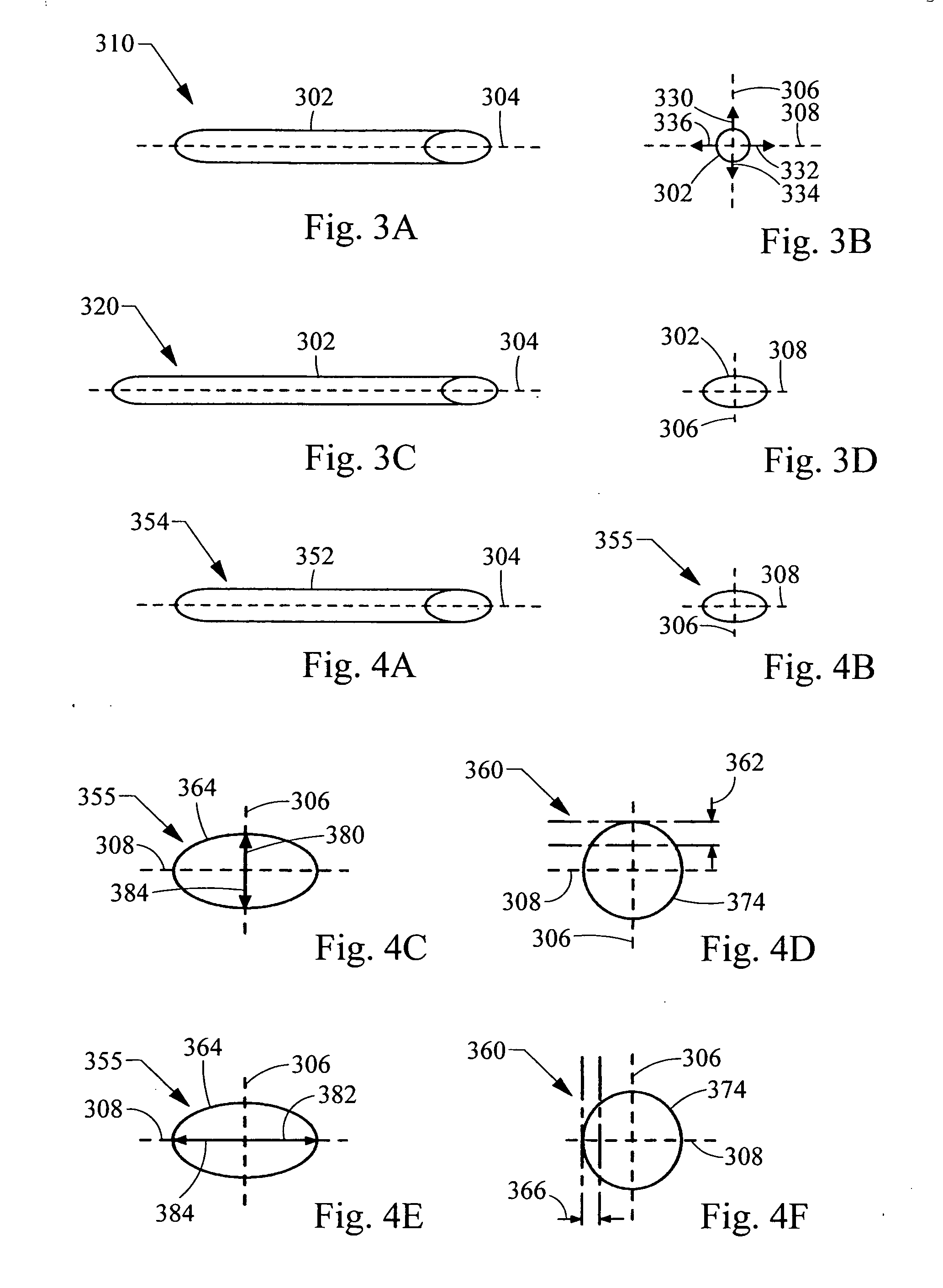
[0044] The frame can also, in a third embodiment, be characterized by a first radial expandability along a first radial direction that is less than a second radial expandability along a second direction.

[0045]“Radial expandability” refers to how easily a given force applied outward from inside the frame can displace the frame outward. The radial expandability can be same or different from the radial compressibility for a given frame embodiment. Radial expandability can be measured by comparing the radial frame displacement in response to a force applied to the frame radially outward, away from the center of the frame, along at least two different directions. Like measuring radial compressibility, the greater the displacement of the frame in response to the applied force in a particular direction, the greater the radial expandability of the frame in that direction.

[0046]FIG. 3A shows perspective view (with corresponding end view of FIG. 3B) of a medical device 300 having a greater e...


PUM


Abstract

Medical devices for implantation in a body vessel, and methods of using and making the same, are provided. Embodiments of the invention relate to medical devices comprising a frame having cross-section that can substantially conform to body vessel shapes that have elliptical or circular cross-sections, and dynamically respond to changes in the cross-section of a body vessel. Frames with directionally-dependent radial compressibility or expandability characteristics are also provided. Medical devices comprising a frame and one or more valve members adapted to regulate fluid flow in a body vessel, such as a vein, are also provided.

Description

RELATED APPLICATIONS [0001] This application claims priority to U.S. Provisional Patent Application Ser. No. 60 / 561,013, filed Apr. 8, 2004, and entitled, “Emplantable Medical Device with Optimized Shape,” which is incorporated by reference herein in its entirety.TECHNICAL FIELD [0002] The present invention relates to medical devices. More particularly, the invention relates to medical devices for implantation in a body vessel. BACKGROUND [0003] Many vessels in animals transport fluids from one body location to another. Frequently, fluid flows in a substantially unidirectional manner along the length of the vessel. For example, veins in the body transport blood to the heart and arteries carry blood away from the heart. [0004] Recently, various implantable medical devices and minimally invasive methods for implantation of these devices have been developed to deliver these medical devices within the lumen of a body vessel. These devices are advantageously inserted intravascularly, for...

Claims


Application Information

Patent Timeline
Patent Type & Authority Applications(United States)
IPC IPC(8): A61F2/00A61F2/24A61F2/90
CPCA61F2/2418A61F2/2475A61F2/90A61F2002/30014A61F2002/3011A61F2230/0054A61F2250/0018A61F2220/0016A61F2220/005A61F2220/0058A61F2230/0017A61F2230/0002A61F2250/0036
Inventor CASE, BRIAN C.FLAGLE, JACOB A.
Owner COOK MEDICAL TECH LLC
Why Eureka
Try Eureka