Control device and footstep determination device for legged mobile robot

a mobile robot and control device technology, applied in the field of legged mobile robots, can solve the problems of angular slippage between the foot and the floor, robot walking straight, and difficult to apply the control system directly for controlling legged mobile robots, and achieve the effect of convenient setup

Active Publication Date: 2005-10-13
HONDA MOTOR CO LTD
View PDF9 Cites 65 Cited by
  • Summary
  • Abstract
  • Description
  • Claims
  • Application Information

AI Technical Summary

Benefits of technology

[0016] The landing positions / orientations of the feet of the robot are less liable to suffer frequent variations than other parts of the robot, such as a body thereof. Even when an angular slippage (spin) occurs between the foot and the floor, any change in the landing position of the foot due to the angular slippage is small, and the stability of a change in the landing orientation is high. Therefore, the landing position / orientation of the foot is stabler as representing a position and moving direction of the robot than the other parts of the robot. Therefore, when a landing position / orientation of the foot is estimated, the estimated landing position / orientation is suitable as representing an actual position and moving direction of the robot. As a result, according to the first invention, the robot can appropriately be guided for movement along a path.
[0072] In the thirty-fifth through thirty-ninth inventions, if the legged mobile robot comprises a biped mobile robot having two legs, the desired landing position for the foot preferably comprises a point having a predetermined positional relationship to each foot and a desired position for a representative point which is determined in advance with respect to each foot such that the representative point with respect to each foot becomes an identical point for both feet when the robot is upstanding in a predetermined reference symmetrical posture (fortieth invention). With this arrangement, since the environment-dependent allowable landing range and the self-dependent allowable landing range are each set up as an allowable range of the position of the representative point and the desired landing orientation of the foot, they can easily be set up.

Problems solved by technology

Generally, legged mobile robots which move by repeating lifting and then landing actions of each of a plurality of legs are problematic in that as the moving speed of the robot increases, the frictional force between the foot at the distal end of a leg and the floor reaches a limit due to reactive forces produced when the leg swings, causing an angular slippage between the foot and the floor, so that the robot as a whole has its posture turned about a vertical axis and tends to deviate from the direction of a desired gait or from a desired path.
Additionally, only a desired gait for keeping the body of a robot in a vertical posture (upstanding posture) at all times and causing the robot to walk straight is not necessarily generated.
However, it has been difficult to apply these control systems directly for controlling legged mobile robots.
First, many regions such as the body of a robot are intensively accelerated and decelerated even while the robot is making one step, and it has been difficult to accurately recognize an actual position and posture (orientation) of those regions.
Furthermore, since the robot can move in any desired directions irrespective of the orientation of the body, the orientation of the body and the traveling direction thereof are not necessarily in agreement with each other.
That is, simply observing an instantaneous motion status of the robot, such as the speed of the body, the orientation of the robot, etc., fails to determine whether the robot is going to deviate from the desired path or not.
Thirdly, since the robot has to be kept in posture balance and the capability limits of actuators must not be exceeded, the robot has been unable to abruptly change the gait.
For example, if the robot is to abruptly change the landing position for a foot thereof immediately before the foot lands on the floor, the robot may be unable to change the landing position because the speeds or forces of actuators may be likely to exceed their limits.
Even when the robot can change the landing position, the robot may possibly be thrown out of balance after the foot has landed on the floor.
As described above, it has been difficult to simply apply the conventional path guidance technology to robots.

Method used


Image

  • Control device and footstep determination device for legged mobile robot
  • Control device and footstep determination device for legged mobile robot
  • Control device and footstep determination device for legged mobile robot

Examples


third embodiment

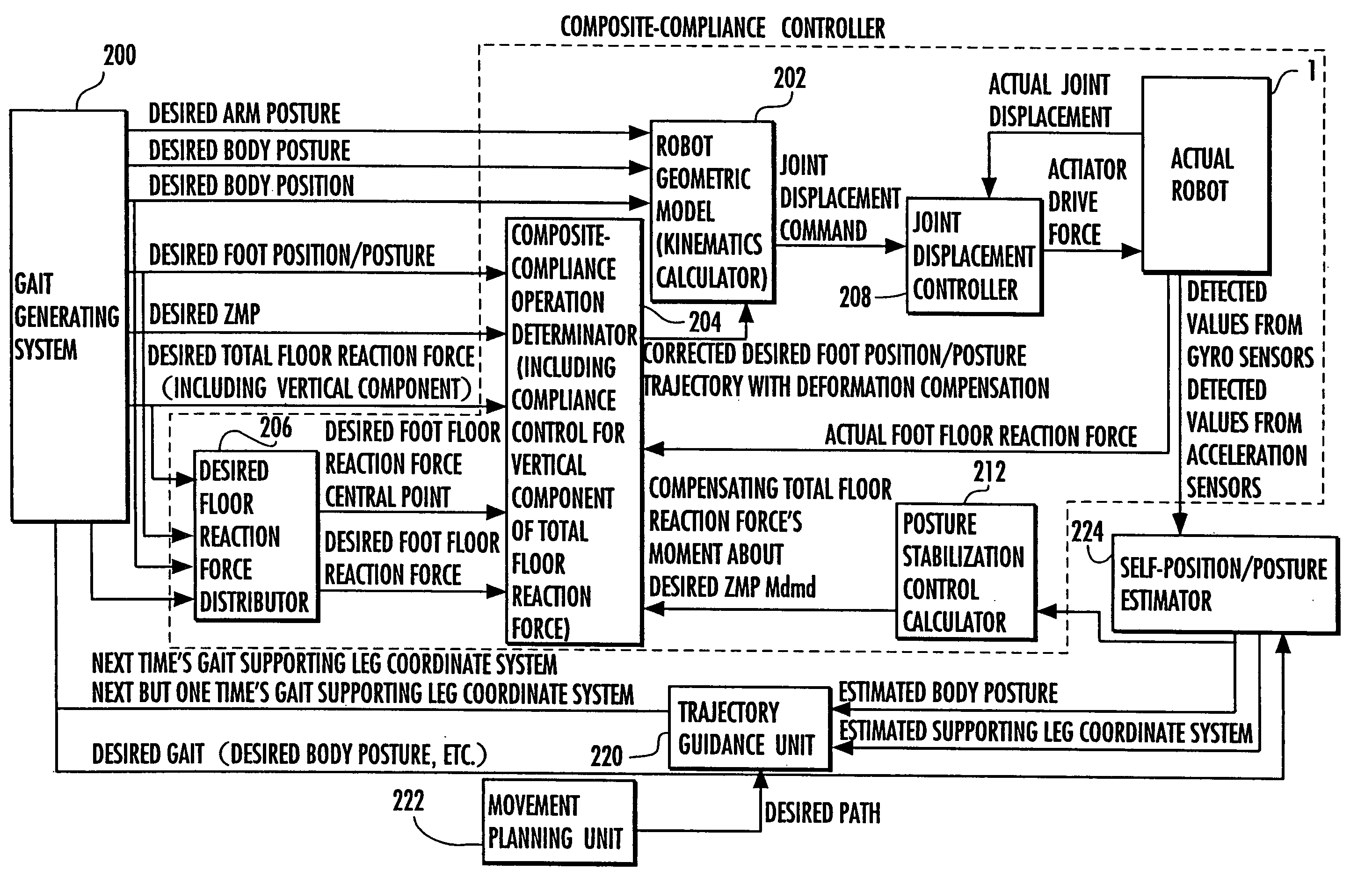
[0153] Then, control goes to S016 in which the self-position / posture estimator 224 performs a self-position / posture estimating process. The self-position / posture estimating process is a process of estimating an actual position and orientation of the robot 1 in a coordinate system (global coordinate system) fixed to the floor (ground) on which the robot 1 moves, and is carried out according to a flowchart shown in FIG. 10. The self-position / posture estimating process adopts a process proposed in an application filed on the same date as the present application (a PCT application claiming priority based on Japanese patent application No. 2002-127066, entitled “Apparatus for estimating self-position of legged mobile robot”), and is described in detail in the PCT application. Therefore, the self-position / posture estimating process will be described only briefly.

[0154] The self-position / posture estimating process is a process of estimating a position / posture of the supporting leg coordina...

first embodiment

[0193] The trajectory guidance process in S022 according to the present invention will be described in detail below.

[0194]FIG. 13 shows a flowchart of the trajectory guidance process.

[0195] In S3000, as shown in FIG. 16, a current time's short-term desired point Q(0) is determined based on the position of a representative point P(0) of the current time's estimated supporting leg coordinate system (the estimated supporting leg coordinate system determined in the preceding control period) and a desired path.

[0196] The desired path is a path along which the actual footstep (a row of landed positions and orientations of the foot 22 of the free leg) of the robot 1 represented by a time sequence of the estimated supporting leg coordinate system is to follow. In the description which follows, the desired path may be referred to as a desired footstep path. The desired footstep path may be set up in advance, but may be generated from time to time in order to reach a desired point while avo...

second embodiment

[0233]FIG. 21 is a flowchart of the trajectory guidance process in S022 in FIG. 9 according to the

[0234] The trajectory guidance process in S022 according to the second embodiment will be described below with reference to FIG. 21. In S3200, a curve C which is asymptotically close from the representative point P(0) to the desired footstep path, as shown in FIG. 22, is determined based on the representative point P(0) of the current time's estimated supporting leg coordinate system (estimated supporting leg coordinate system determined in S016 shown in FIG. 9 in the control period at the current time t) and the desired path (desired footstep path). Specifically, a curve C is determined to be a trajectory for an unmanned vehicle or an automatically driven vehicle under trajectory guidance control to be asymptotically close to the desired path.

[0235] More specifically, if a point of intersection between a perpendicular line extending from an optional point A on the curve C to the desir...


PUM


Abstract

A landing position / orientation of a foot (22) to be landed in a landing action of a robot (1) such as a biped mobile robot or the like is estimated, and a desired footstep path for the robot (1) is set up. Based on the estimated landing position / orientation and the desired footstep path, a future desired landing position / orientation is determined in order to cause actual footsteps of the robot (1) (a sequence of landing positions / orientations of the foot (22)) to approach desired footsteps. Using at least the determined desired landing position / orientation, a desired gait for the robot (1) is determined, and the robot (1) is controlled in operation depending on the desired gait. For determining the desired landing position / orientation, mechanism-dependent limitations of the robot (1) such as an interference between the legs thereof, etc., and limiting conditions of an allowable range in which a desired ZMP can exist are taken into consideration.

Description

TECHNICAL FIELD [0001] The present invention relates to a legged mobile robot such as a biped mobile robot or the like, and more particularly to an apparatus for guiding the path (guiding the trajectory) of such a legged mobile robot. BACKGROUND ART [0002] Generally, legged mobile robots which move by repeating lifting and then landing actions of each of a plurality of legs are problematic in that as the moving speed of the robot increases, the frictional force between the foot at the distal end of a leg and the floor reaches a limit due to reactive forces produced when the leg swings, causing an angular slippage between the foot and the floor, so that the robot as a whole has its posture turned about a vertical axis and tends to deviate from the direction of a desired gait or from a desired path. [0003] Additionally, only a desired gait for keeping the body of a robot in a vertical posture (upstanding posture) at all times and causing the robot to walk straight is not necessarily g...

Claims


Application Information

Patent Timeline
IPC IPC(8): B62D57/02B62D57/032
CPCB62D57/032B25J13/085B25J13/00
Inventor TAKENAKA, TORUMATSUMOTO, TAKASHI
Owner HONDA MOTOR CO LTD
Why Eureka
Try Eureka