Coding system and decoding system

a coding system and decoding technology, applied in the field of coding system and decoding system, can solve the problems of difficult to form a code word, difficult to combine with a synchronous recovery technique for recovering, and difficulty in forming a code word, so as to improve information quality, improve coding efficiency, and reduce the number of inserted bits

Inactive Publication Date: 2005-10-13
KK TOSHIBA
View PDF56 Cites 16 Cited by
  • Summary
  • Abstract
  • Description
  • Claims
  • Application Information

AI Technical Summary

Benefits of technology

[0016] It is therefore a principal object of the present invention to eliminate the aforementioned problems and to provide coding and decoding systems, which can prevent a pseudo synchronization and a step out due to the error detection of a synchronization code.
[0017] It is another object of the present invention to provide coding and decoding systems, which prevent a pseudo synchronization and a step out due to the error detection when an error correction / detection coding is combined with a synchronization recovering technique using a synchronization code.
[0018] It is further object of the present invention to provide coding and decoding systems, which can decrease the number of inserted bits used at the end portion in a synchronization interval to enhance the coding efficiency, when an error correction / detection coding is combined with a synchronization recovering technique using a synchronization code.

Problems solved by technology

However, in such a method for coding a code string obtained by a high-efficiency compression coding into error correcting / detecting codes to transmit and / or store the codes, there is a disadvantage in that it is difficult to be combined with a synchronous recovering technique for recovering a step out caused by a code word error in the transmission line / medium.
However, in an error correction- / detection coding, it is generally difficult to form a code word so as to prevent a certain bit pattern from occurring.
When the same bit pattern as the synchronization code occurs, a pseudo synchronization may be caused by the error detection of the synchronization code.
However, in a case where the code string is transmitted and / or stored via a medium in which errors are easy to occur, errors may occur in the inserted bit, so that there is a problem in that a new step out or a new pseudo synchronization may occur.
In addition, in a case where the error correction / detection coding of a code string is carried out to insert a synchronization code, there is also a problem in that the coding efficiency is lowered since it is required to add many inserted bits to the code string in order to compensate an excess of information bits, for which the error detection and / or detection coding is to be carried out, at the end portion of a synchronization interval between the adjacent synchronization codes.
However, in the method for switching the error correcting / detecting codes by adding such a header information, there is a problem in that the number of bits of the code string to be transmitted and / or stored by adding the header information is increased.
In a case where the picture and / or voice information is high-efficiency compression coded to be transmitted and / or stored, if the number of bits is occupied by the header information, the number of bits used for the high-efficiency compression coding of the picture and / or voice information is decreased, so that the picture quality and sound quality are deteriorated.
Therefore, in a case where the error correction- / detection coding is combined with the synchronous recovering technique using a uniformly decodable synchronization code, there is a problem in that a pseudo synchronization is caused by the error detection of the synchronization code.
Also in a case where the dummy bit is inserted to prevent the pseudo synchronization, there is a problem in that a new step out or a new pseudo synchroni-zation is caused by the error of the inserted bit.
In addition, in a case where the error correction- / detection coding of the code string is performed and the synchronization code is inserted, it is conventionally required to use many inserted bits to compensate an excess of information bits, for which the error detection and / or detection coding is to be carried out, at the end portion of a synchronization interval between the adjacent synchronization codes, so that there is a problem in that the coding efficiency is lowered.
Therefore, in a case where a picture and / or voice information is high-efficiency compression coded to be transmitted and / or stored, there is a problem in that the information content assigned to the picture and / or voice information is decreased to lower the picture quality and the sound quality.

Method used


Image

  • Coding system and decoding system
  • Coding system and decoding system
  • Coding system and decoding system

Examples


first preferred embodiment

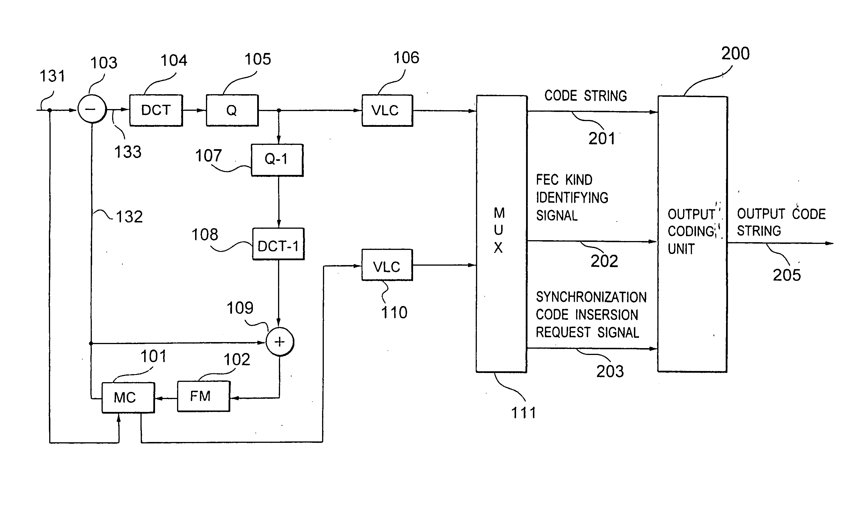
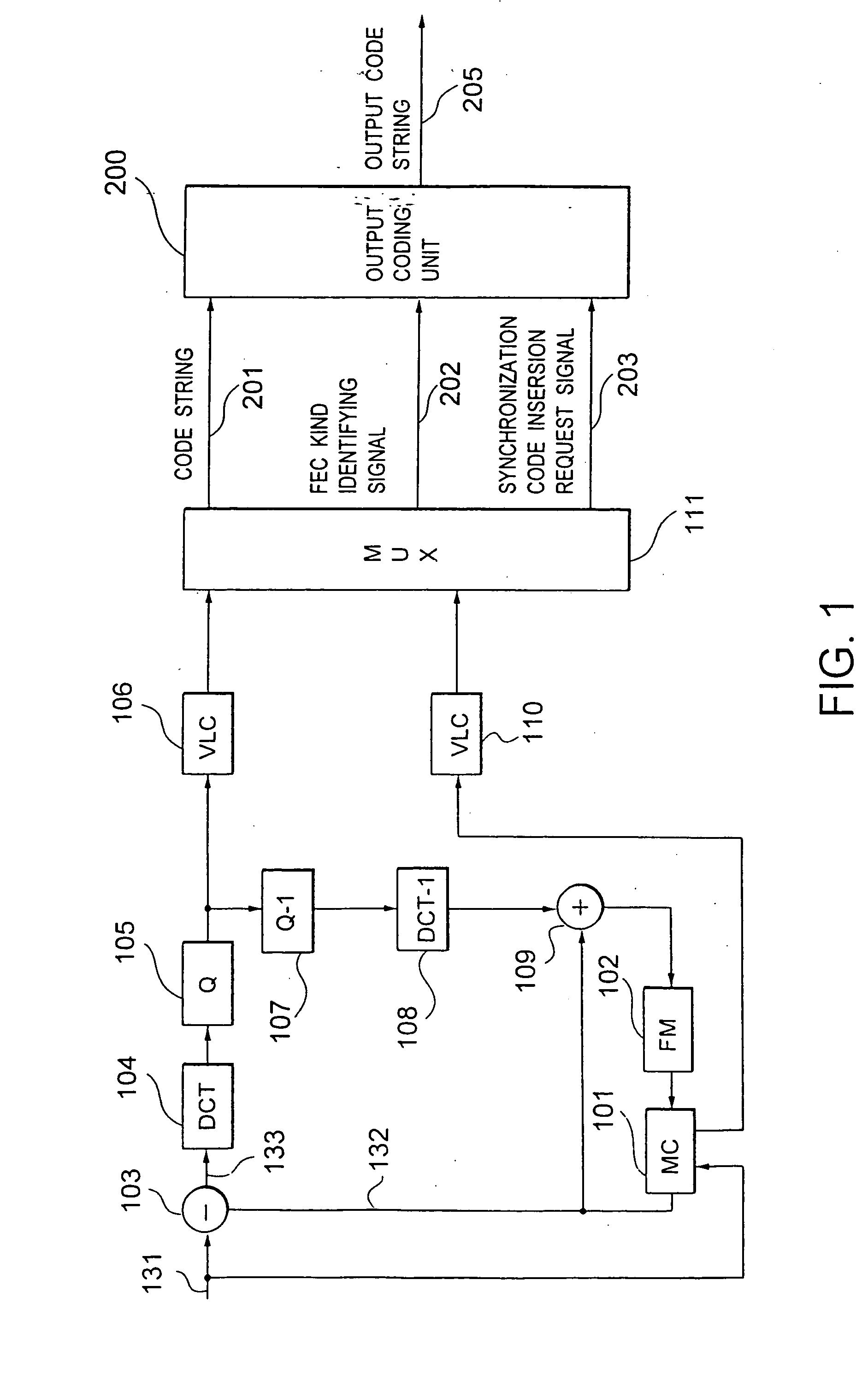
[0093]FIG. 1 is a block diagram of the first preferred embodiment of a dynamic image coding system, according to the present invention, wherein a coding system having an error correcting / detecting code switching function of the present invention is combined with a high-efficiency compression coding system which uses a motion-compensated adaptive prediction and a discrete cosine transform coding serving as a kind of an orthogonal transform coding. A coding system comprising the combination of a motion-compensated adaptive prediction and a discrete cosine coding is detailed in, e.g., Literature 1 “International Standard of Multimedia Coding” by Hiroshi Yasuda, Maruzen (June 1991). Therefore, only the operation of the coding system will be schematically described. In addition, it is assumed that information bits are separated from detection bits in an error correcting / detecting code similar to a BCH code.

[0094] In FIG. 1, with respect to an input dynamic image signal 131 serving as an...

second preferred embodiment

[0149] Referring to FIGS. 12 through 14, the second preferred embodiment of the present invention will be described below.

[0150] In this preferred embodiment, a dynamic image coding system and a dynamic image decoding system can surely detect synchronization even if a code string is transmit-ted / stored in a transmission line / storage medium in which the number of bits is decreased due to the loss of a part of a bit string or the number of bits is increased due to the addition of excessive bits.

[0151]FIG. 12 is a block diagram showing the principle of a process for detecting synchronization when such addition- / loss of bits occurs. It is assumed herein that the right synchronization code comprises “0”s of sync—0_len bits and a “1” of one bit as shown in FIG. 12(a). Furthermore, in FIG. 12, “x” denotes a bit other than a synchronization code.

[0152] FIGS. 12(b) through 12(e) show how the synchronization code is changed by the addition / loss of bits. It is assumed herein that the number...

third preferred embodiment

[0180] The third preferred embodiment of the present invention will be described below. In this preferred embodiment, the error correcting / detecting code is not used. At this point, this preferred embodiment is different from the first and second preferred embodiments.

[0181]FIG. 18 is a block diagram of a dynamic image coding system in this preferred embodiment. Using the same reference numbers as those in FIG. 1 for the parts corresponding to those in FIG. 1, the different points from the first preferred embodiment will be mainly described. In this preferred embodiment, the construction and operation of an output coding unit 200 are different. In addition, although the basic operation of a multiplexer 111 is the same as the multiplexer 111 of FIG. 1, the multiplexer 111 in this preferred embodiment outputs only a multiplexed code string 201 and a synchronization code insertion request signal 203 since the error correcting- / detecting code is not used.

[0182]FIG. 19 is a block diagr...


PUM

PropertyMeasurementUnit
lengthaaaaaaaaaa
transmission rateaaaaaaaaaa
error resistanceaaaaaaaaaa

Abstract

In a coding system wherein an error correction / detect-ion coding is combined with a synchronization recovering technique using a synchronization code, the problems of a pseudo synchronization and a step out due to error detect-ion are solved. There is provided a coding part 212 for coding an input multiplexed code string 201 to an error correcting- / detecting code comprising an information bit and a check bit, and code string assembling part 213 for inserting a synchronization code into any one of a plurality of periodically predetermined synchronization code inserting positions in the code string 201, for arranging the information bit at an optional position in the code string, and for arranging the check bit at a position other than the synchronization code inserting positions in the code string 201 to assemble an output code string 205.

Description

TECHNICAL FIELD [0001] The present invention relates generally to a system for transmitting and / or storing information via a medium of a high error rate, such as a radio transmission line. More specifically, the invention relates to a coding and / or decoding system suited to carry out the error correction / detection coding of a compressed code string obtained by the high efficiency compression coding to transmit and / or store the compressed code string. BACKGROUND ART [0002] For example, in a system for carrying out the high-efficient compression coding of a picture and / or voice information so as to have a small information content to transmit the compression-coded picture and / or voice information via a radio transmission line, such as a radio visual telephone, a portable information terminal and a digital television broadcast system, it is important how to transmit the obtained code string with a high quality since the transmission line has a high error rate. [0003] In a case where a ...

Claims


Application Information

Patent Timeline
Patent Type & Authority Applications(United States)
IPC IPC(8): G11B20/18G11B27/30H03M13/00H03M13/33H04J3/06H04L1/00H04L7/04H04N7/50H04N7/56H04N7/66H04N19/89
CPCG11B20/1813H04N19/68H03M13/15H03M13/152H03M13/23H03M13/33H03M13/356H04J3/0602H04L1/0042H04L1/007H04L1/0079H04L1/0083H04L7/041H04L7/048H04L2001/0098H04N7/56H04N19/00H04N19/70H04N19/61H04N19/89G11B27/3027H04L1/0041H04L1/0047H04L1/0068H04L1/0075
Inventor KIKUCHI, YOSHIHIROWATANABE, TOSHIAKIDACHIKU, KENSHICHUJOH, TAKESHINAGAI, TAKESHI
Owner KK TOSHIBA
Why Eureka
Try Eureka