Shifted channel characteristics for mitigating co-channel interference

a channel and co-channel technology, applied in the field of communication systems, to achieve the effect of minimizing co-channel interference and minimizing co-channel interferen

Active Publication Date: 2005-10-13
DTVG LICENSING INC
View PDF24 Cites 32 Cited by
  • Summary
  • Abstract
  • Description
  • Claims
  • Application Information

AI Technical Summary

Benefits of technology

[0031] To minimize the limitations in the prior art, and to minimize other limitations that will become apparent upon reading and understanding the present specification, the present invention discloses methods and apparatuses for minimizing co-channel interference in communications systems. A method in accordance with the present invention comprises shifting a characteristic of the first signal with respect to a like characteristic of the second signal to mitigate co-channel interference, and transmitting the first signal and the second signal over different channels of the communication system.

Problems solved by technology

Such interference is called “co-channel” interference, where one channel of data interferes with the reception and demodulation of another channel of data.

Method used


Image

  • Shifted channel characteristics for mitigating co-channel interference
  • Shifted channel characteristics for mitigating co-channel interference
  • Shifted channel characteristics for mitigating co-channel interference

Examples


Embodiment Construction

[0049] An apparatus, method, and software for reducing co-channel interference in a digital broadcast and interactive system are described. In the following description, reference is made to the accompanying drawings which form a part hereof, and which show, by way of illustration, several embodiments of the present invention. It is understood that other embodiments may be utilized and structural changes may be made without departing from the scope of the present invention.

Overview

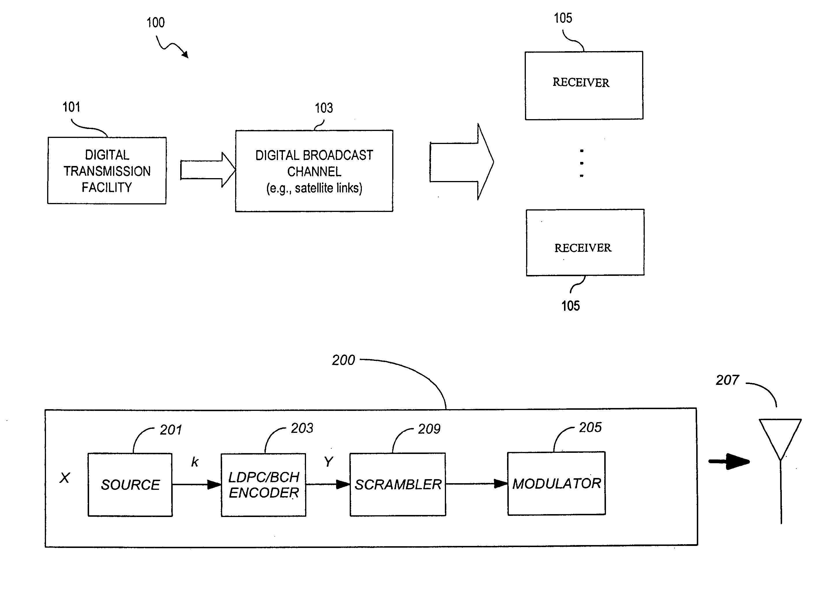
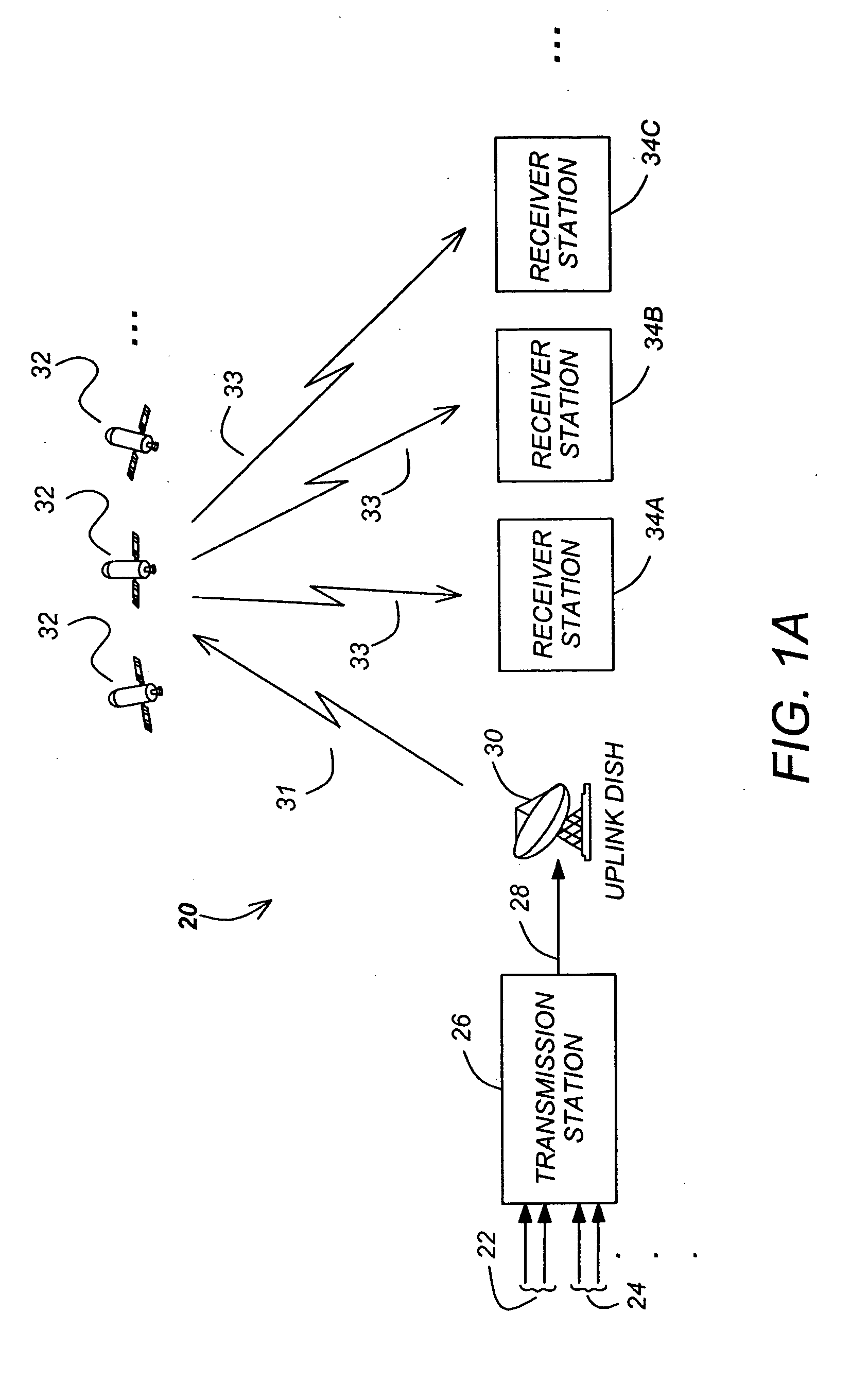
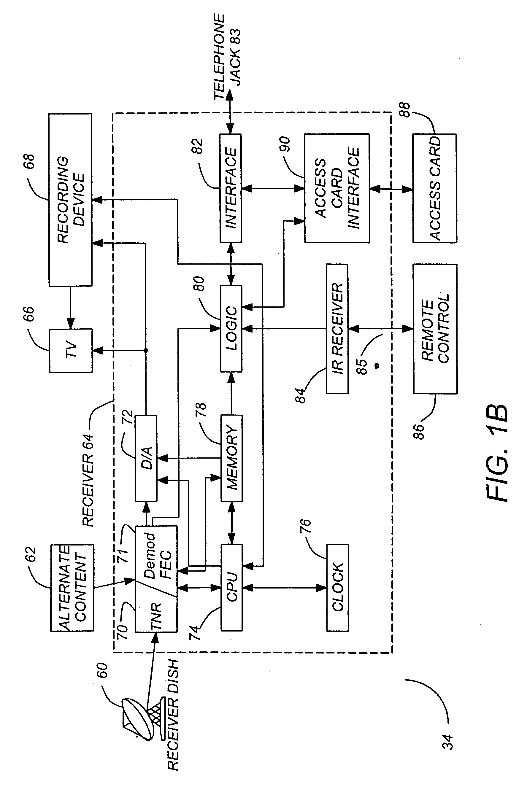
[0050] In the present invention, the digital data transmitted from transmission station 26 via signal 31, satellites 32, and signal 33 contains three main components: a header portion of a data frame, called the physical layer header, or PL header, and payload data, and optionally, additional inserted symbols, called pilot symbols, which are used by the receiver 64 to mitigate the deleterious effects of degradation in the receiver station 34, primarily phase noise. By using the PL header, the demodulato...


PUM


Abstract

Methods and apparatuses for minimizing co-channel interference in communications systems are disclosed. A method in accordance with the present invention comprises shifting a characteristic of the first signal with respect to a like characteristic of the second signal to mitigate co-channel interference, and transmitting the first signal and the second signal over different channels of the communication system.

Description

CROSS REFERENCE TO RELATED APPLICATION [0001] This application claims the benefit of the earlier filing date under 35 U.S.C. § 119(e) of U.S. Provisional Application Ser. No. 60 / 561,418 filed Apr. 12, 2004, entitled “Co-channel Interference Mitigation for DVB-S2”; the entirety of which are incorporated herein by reference.BACKGROUND OF THE INVENTION [0002] 1. Field of the Invention [0003] The present invention relates to communication systems, and more particularly to methods and apparatuses for minimizing signal interference. [0004] 2. Description of the Related Art [0005]FIGS. 1A and 1B illustrate a typical satellite based broadcast systems of the related art. [0006]FIG. 1A shows a communications system, specifically a television broadcasting system 20, which transmits and receives audio, video, and data signals via satellite. Although the present invention is described in the context of a satellite-based television broadcasting system, the techniques described herein are equally ...

Claims


Application Information

Patent Timeline
Patent Type & Authority Applications(United States)
IPC IPC(8): H04B7/185H04L9/00H04N5/21H04N7/16H04N7/167H04N7/173
CPCH04B7/18513H04B7/1858H04N5/211H04N7/16H04N21/6143H04N7/1675H04N7/17318H04N21/2347H04N21/4405H04N7/163H04N7/173H04N5/445H04N21/235
Inventor SANTORU, JOSEPHCHEN, ERNEST C.MAITRA, SHAMIKLAI, DENNISZHOU, GUANGCAILIN, TUNG-SHENG
Owner DTVG LICENSING INC
Why Eureka
Try Eureka