
Method, device and cartridge for measuring fluctuations in the cross-sectional area of hair in a pre-determined scalp area

a technology of cross-sectional area and scalp area, which is applied in the direction of instruments, applications, person identification, etc., to achieve the effects of reducing hair diameter, easy to perform, and measuring fluctuations in the cross-sectional area of a section of hair

Active Publication Date: 2005-10-20
BERNARD COHEN TECH LLC
View PDF12 Cites 15 Cited by
  • Summary
  • Abstract
  • Description
  • Claims
  • Application Information

AI Technical Summary

Benefits of technology

[0022] According to the present invention there is provided a method and device for measuring fluctuations in the cross sectional area of a section of hair as it relates to the quantification and clinical course of medical hair loss disorders or the effectiveness or progress of hair loss treatment. The method and device are used for determining the cumulative cross-section of hairs within a pre-measured area. The method and device uses a much larger sample of scalp surface than the hair weight method, hair count method, and hair cutting is not required. The length of the hair is not considered a factor in the evaluation because of wide variations of individual styling would make it impossible, and clinically irrelevant. The method of the present invention is easy to perform in a non-laboratory setting and employs a new hand-held device. The method and device allow physicians and hair care professionals to track and document the status of patients, suffering from scalp hair thinning or shedding, at any time in the course of their evaluation or treatment. The method and device may be used to quantitatively evaluate the effectiveness of hair growing preparations and drugs and quantify the severity and clinical course of other medical hair loss disorders. The method and device may be used to detect early decreases in hair diameter—the predictive hallmark of balding—many years before it is apparent.
[0027] The bundle is captured in the slot and automatically immobilized against the anvil on the boss. The slot is 1 mm wide and preferably between 7-12 mm high and relative movement between the anvil and the slot measures the height of the hair. By engaging the heavy compression spring, the load on the column of trapped hair may be precisely maintained and thereby kept constant in repeated measurements. This is important because the hair bundle is quite compressible. The mm height of the hair column is displayed on an LED window of an integrated micrometer head that causes relative movement between the anvil and the slot. If a mechanical height-measuring gauge is incorporated in the design of the device, it is displayed on the face of an analog dial. If an electronic height-measuring gauge is incorporated into the device, the height is displayed on an LED window. The height of hair in the trapping hair-receiving slot is expressed as an arbitrary value that shall be called the density-diameter index, the hair mass, the hair mass index, the cross-sectional index, the cumulative cross-sectional index, or the combined cross-sectional index.

Problems solved by technology

The length of the hair is not considered a factor in the evaluation because of wide variations of individual styling would make it impossible, and clinically irrelevant.

Method used


Image

  • Method, device and cartridge for measuring fluctuations in the cross-sectional area of hair in a pre-determined scalp area
  • Method, device and cartridge for measuring fluctuations in the cross-sectional area of hair in a pre-determined scalp area
  • Method, device and cartridge for measuring fluctuations in the cross-sectional area of hair in a pre-determined scalp area

Examples


Embodiment Construction

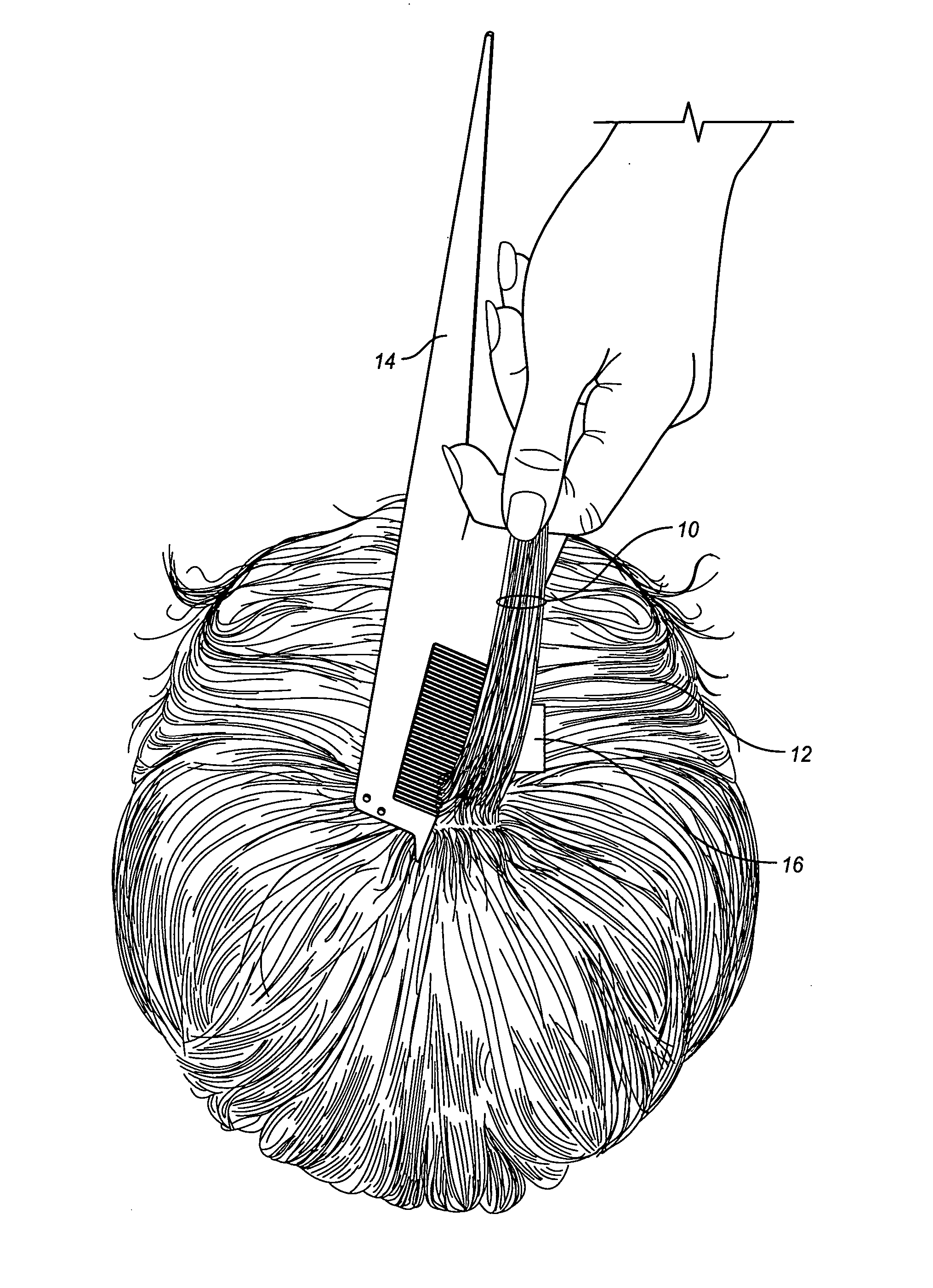
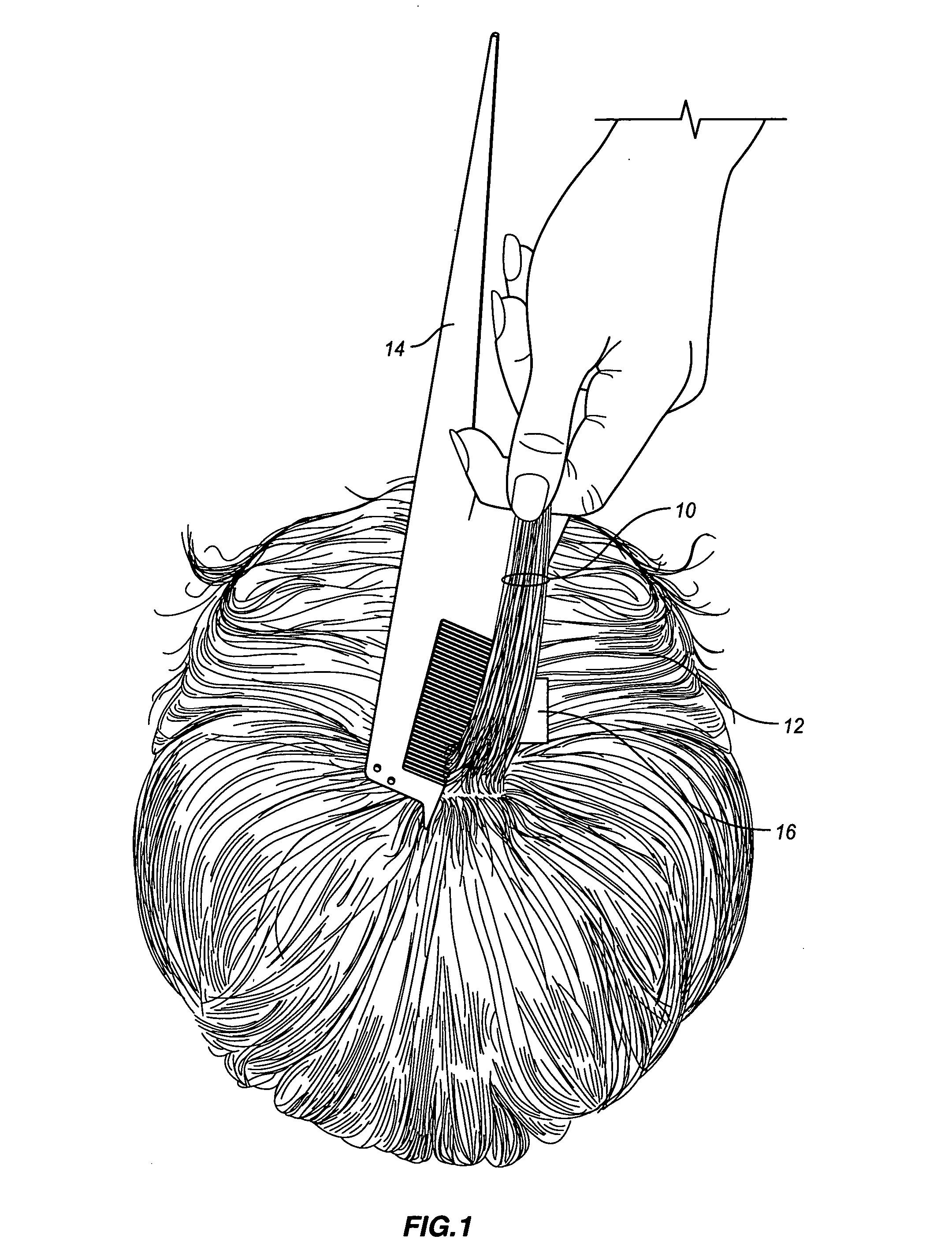
[0048] Referring now to FIG. 1 there is illustrated therein a combed bundle or section of hair 10 from a scalp 12, that has been combed with a comb or combing element 14. The bundle 10 of hair is delineated from a predetermined area of the scalp 12 by a gummed label 16, without cutting the bundle 10 of hair.

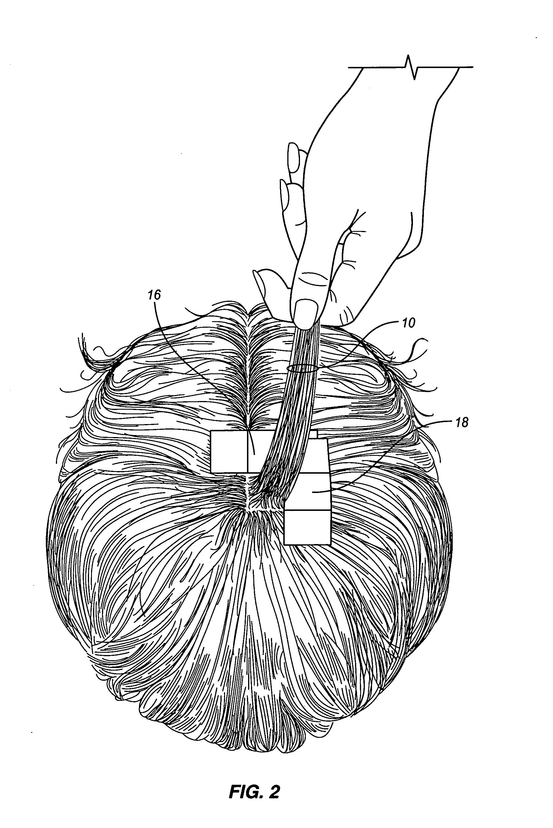
[0049] As shown in FIGS. 2-4, sequentially the delineated area of the scalp is fixed by gummed labels 18, 20 and 22. Each gummed label has a centimeter scale printed thereon so that the predetermined area, e.g., 2 square centimeters, can be measured and segregated by the gummed labels 16, 18, 20 and 22 from the rest of the hair on the scalp. The gummed labels 16, 18, 20 and 22 are printed with scale lines at intervals 2 cm apart. The color-coded lines are aligned with the edge of the preceding label and overlapped in a 4 step sequential fashion to create an isolated field of uncut hair that is 2 cm square.

[0050] Preferably, a 2×2 cm of scalp hair is manually isolated by combing...


PUM


Abstract

A flexible measuring tape is extended from a predetermined location on a face a predetermined distance to a location on a scalp. A 2 cm by 2 cm square bundle of hair about that location is isolated. The bundle of isolated hair is captured in a slit in a two-part cartridge, one part being slidable in the other part about a changeable length slit 1 mm wide. The cartridge is placed in an “L” shaped end of a plunger extending from a first end of a body of a measuring device. The plunger is drawn into the body of the device to compress the hair in the changeable length slit as the two parts of the cartridge are pushed together between an end of the “L” and the first end of the body. A spring is provided on the plunger between a second end of the body of the device and an inner end of a knob at an outer end of the plunger. The spring applies the same load regardless of the bundle's size and urges the “L” shaped end toward the body to compress the bundle of hair and the amount of compressed hair is read off of a gauge as DDI, Density-Diameter Index, which represents the cross-sectional area of the compressed bundle of hair. After the measurement is made, the smaller part is pulled part way out of the larger part of the cartridge so the cartridge easily can be pulled off of the bundle of hair and discarded.

Description

CROSS REFERENCE TO RELATED APPLICATIONS [0001] This application is a continuation in part of U.S. application Ser. No. 10 / 826,943, filed Apr. 16, 2004.BACKGROUND OF THE INVENTION [0002] 1. Field of the Invention [0003] The present invention relates to a method, device and a two piece cartridge for measuring fluctuations in the cross sectional area of a bundle of hair for the purpose of documenting the clinical course of medical hair loss disorders and the effectiveness of hair growth treatments and / or for the purpose of indirectly calculating the severity of balding disorders or efficacy of hair growth treatment as evidenced by a decrease or increase in hair population and / or hair shaft diameter. [0004] 2. Description of the Related Art [0005] Heretofore, a hair volume-measuring device used for measure of hair damage was disclosed in the Kabacoff et al. U.S. Pat. No. 4,665,741. [0006] Also, see the hair measurement methods disclosed in “Current and Novel Methods for Assessing Effica...

Claims


Application Information

Patent Timeline
IPC IPC(8): A61B5/103A61B5/107G01B3/18G01B3/20G01B5/08
CPCA61B5/1072A61B5/448G01B5/08G01B3/205G01B3/18A61B5/103
Inventor COHEN, BERNARD H.
Owner BERNARD COHEN TECH LLC
Learn More