
Apparatus and methods for utilizing a downhole deployment valve

a technology of deployment valve and deployment valve, which is applied in the direction of fluid removal, borehole/well accessories, survey, etc., can solve the problems of underbalanced or near underbalanced drilling, overbalanced wells, and expense of mud and damage to formations,

Inactive Publication Date: 2005-10-20
WEATHERFORD TECH HLDG LLC
View PDF72 Cites 93 Cited by
  • Summary
  • Abstract
  • Description
  • Claims
  • Application Information

AI Technical Summary

Benefits of technology

[0012] The invention generally relates to methods and apparatus for utilizing a downhole deployment valve (DDV) system to isolate a pressure in a portion of a bore. The DDV system can include fail safe features such as selectively extendable attenuation members for decreasing a falling object's impact, a normally open back-up valve member for actuation upon failure of a primary valve member, or a locking member to lock a valve member closed and enable disposal of a shock attenuating material on the valve member. Actuation of the DDV system can be electrically operated and can be self contained to operate automatically downhole without requiring control lines to the surface. Additionally, the actuation of the DDV can be based on a pressure supplied to an annulus.

Problems solved by technology

Overbalanced wells may still include a blow out preventer in case of a pressure surge.
Disadvantages of operating in the overbalanced condition include expense of the mud and damage to formations if the column of mud becomes so heavy that the mud enters the formations.
Therefore, underbalanced or near underbalanced drilling may be employed to avoid problems of overbalanced drilling and encourage the inflow of hydrocarbons into the wellbore.
Since underbalanced well conditions can cause a blow out, underbalanced wells must be drilled through some type of pressure device such as a rotating drilling head at the surface of the well.
Actuation systems for the DDV often require an expensive control line that may be difficult or impossible to land in a subsea wellhead.
Hydraulic control lines require crush protection, present the potential for loss of hydraulic communication between the DDV and its surface control unit and can have entrapped air that prevents proper actuation.
Furthermore, the actuation system typically requires a physical tie to the surface where an operator that is subject to human error must be paid to monitor the control line pressures.
An object accidentally dropped onto the DDV that is closed during tripping of the tool string presents a potential dangerous condition.
Thus, the object may damage the DDV due to the weight and speed of the object upon reaching the DDV, thereby permitting the stored energy of the pressure below the DDV to bypass the DDV and either eject the dropped object from the wellbore or create a dangerous pressure increase or blow out at the surface.

Method used


Image

  • Apparatus and methods for utilizing a downhole deployment valve
  • Apparatus and methods for utilizing a downhole deployment valve
  • Apparatus and methods for utilizing a downhole deployment valve

Examples


Embodiment Construction

[0030] The invention generally relates to methods and apparatus for utilizing a downhole deployment valve (DDV) in a wellbore. For some of the embodiments shown, the DDV may be any type of valve such as a flapper valve or ball valve. Additionally, any type of actuation mechanism may be used to operate the DDV for some of the embodiments shown.

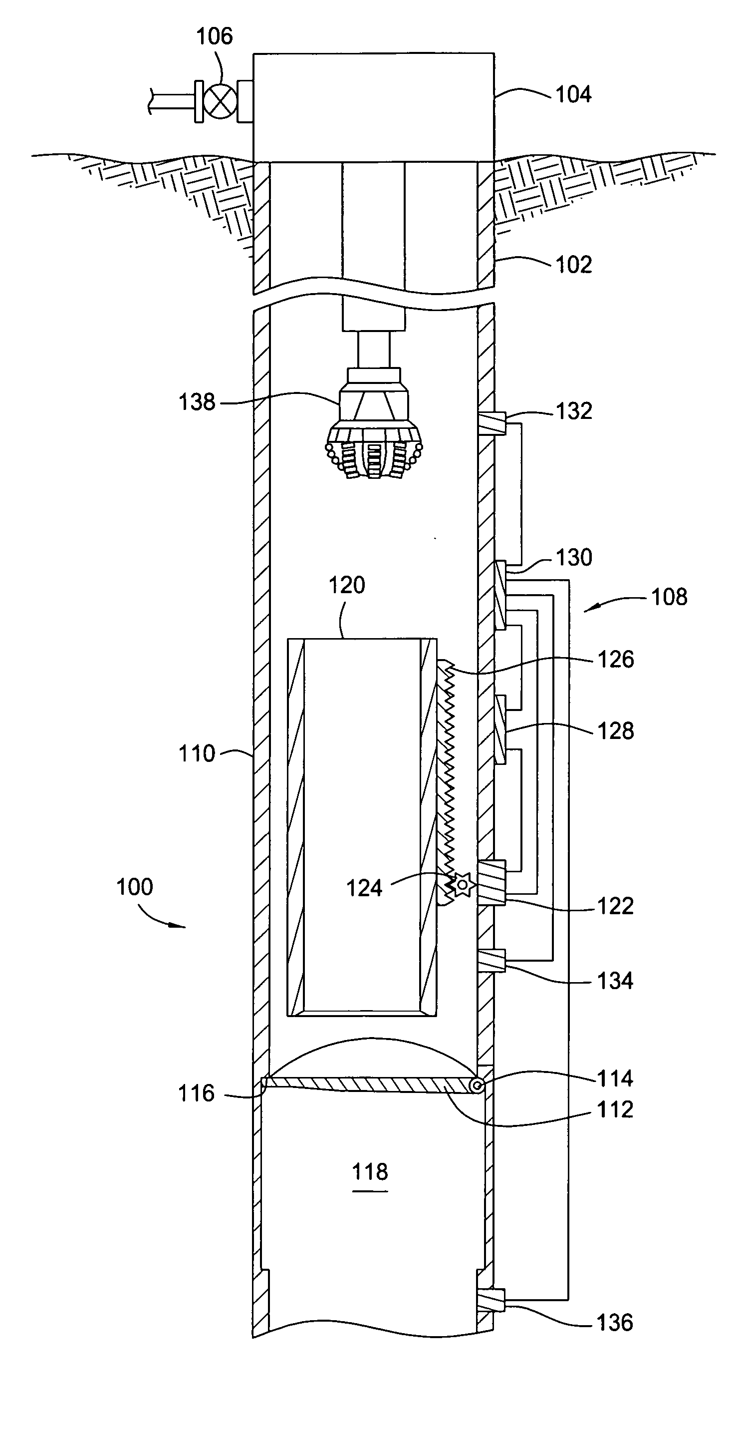
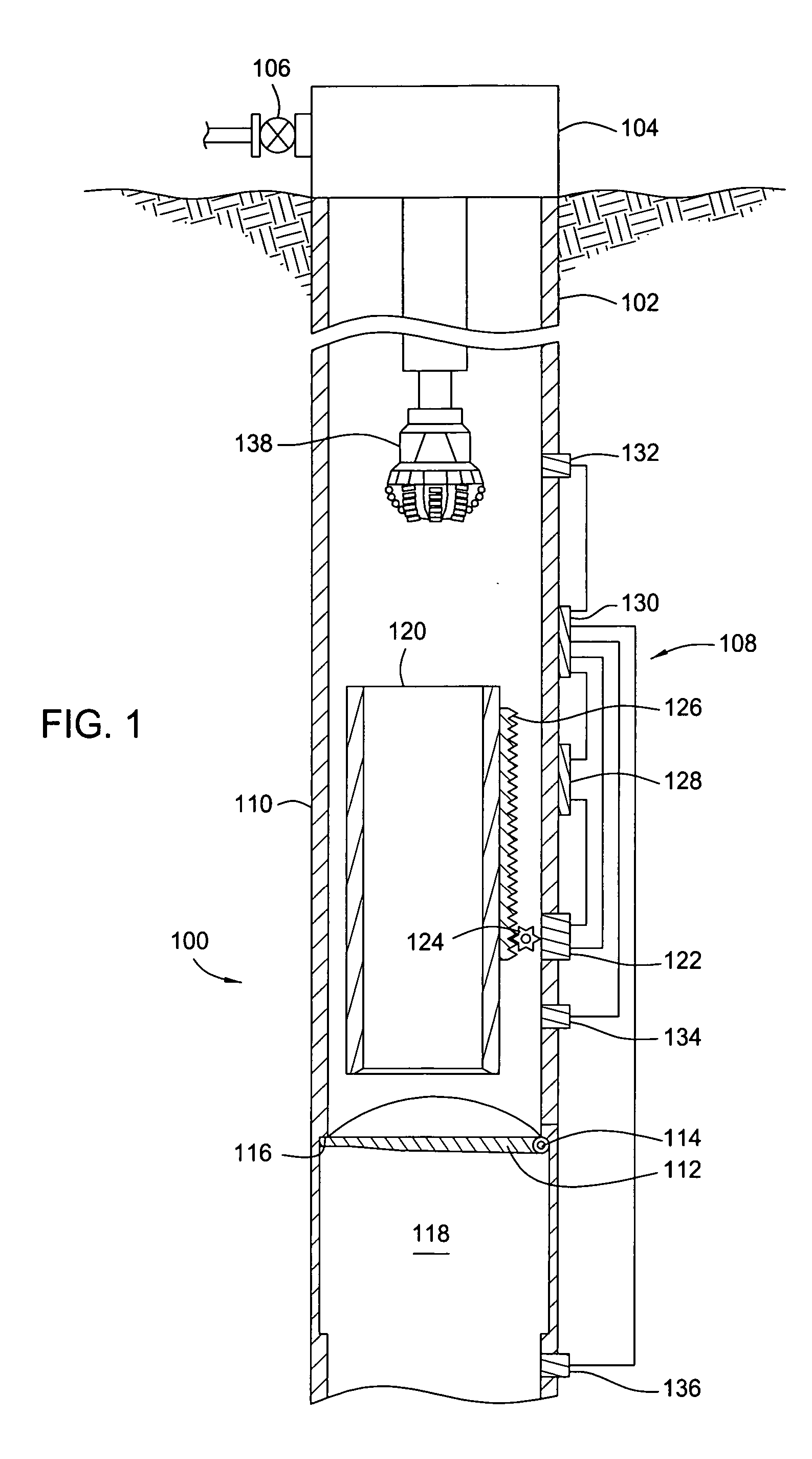
[0031]FIG. 1 illustrates a downhole deployment valve (DDV) 100 within a casing string 102 disposed in a wellbore. The casing string 102 extends from a surface of the wellbore where a wellhead 104 would typically be located along with some type of valve assembly 106 which controls the flow of fluid from the wellbore and is schematically shown. The DDV 100 includes an electrically operated actuation and sensor system 108 self contained downhole, a housing 110, a flapper 112 having a hinge 114 at one end, and a valve seat 116 in an inner diameter of the housing 110 adjacent the flapper 112. Arrangement of the flapper 112 allows it to close in an ...


PUM


Abstract

Methods and apparatus for utilizing a downhole deployment valve (DDV) to isolate a pressure in a portion of a bore are disclosed. The DDV system can include fail safe features such as selectively extendable attenuation members for decreasing a falling object's impact, a normally open back-up valve member for actuation upon failure of a primary valve member, or a locking member to lock a valve member closed and enable disposal of a shock attenuating material on the valve member. Actuation of the DDV system can be electrically operated and can be self contained to operate automatically downhole without requiring control lines to the surface. Additionally, the actuation of the DDV can be based on a pressure supplied to an annulus.

Description

CROSS-REFERENCE TO RELATED APPLICATIONS [0001] This application is a continuation-in-part of co-pending U.S. patent application Ser. No. 10 / 270,015, filed Oct. 11, 2002; is a continuation-in-part of co-pending U.S. patent application Ser. No. 10 / 288,229, filed Nov. 5, 2002; and is a continuation-in-part of co-pending U.S. patent application Ser. No. 10 / 783,982, filed Feb. 20, 2004, which is a continuation in part of U.S. patent application Ser. No. 10 / 677,135, filed Oct. 1, 2003, and U.S. patent application Ser. No. 10 / 676,376, filed Oct. 1, 2003, and which claims benefit of U.S. Provisional Patent Application Ser. No. 60 / 485,816, filed Jul. 9, 2003, all herein incorporated by reference in their entirety.BACKGROUND OF THE INVENTION [0002] 1. Field of the Invention [0003] Embodiments of the invention generally relate to methods and apparatus for use in oil and gas wellbores. More particularly, the invention relates to methods and apparatus for utilizing deployment valves in wellbores...

Claims


Application Information

Patent Timeline
Patent Type & Authority Applications(United States)
IPC IPC(8): E21B34/06E21B34/14E21B41/00
CPCE21B41/0021E21B34/06E21B34/00
Inventor NOSKE, JOEBRUNNERT, DAVID J.PAVEL, DAVIDBANSAL, R. K.HAUGEN, DAVIDLUKE, MIKE A.
Owner WEATHERFORD TECH HLDG LLC
Learn More