

Master cylinder
a technology of master cylinder and cylinder head, which is applied in the direction of braking system, braking components, transportation and packaging, etc., can solve the problems of not being able to sufficiently restrict the reverse fluid flow from the pressure chamber into the reservoir, the efficiency of the braking system is not good, and the fluid cannot be drawn smoothly from the reservoir into the pressure chamber. , to achieve the effect of smooth drawing, good responsiveness and simple structur
- Summary
- Abstract
- Description
- Claims
- Application Information
AI Technical Summary
Benefits of technology
Problems solved by technology
Method used
Image

Examples
Embodiment Construction
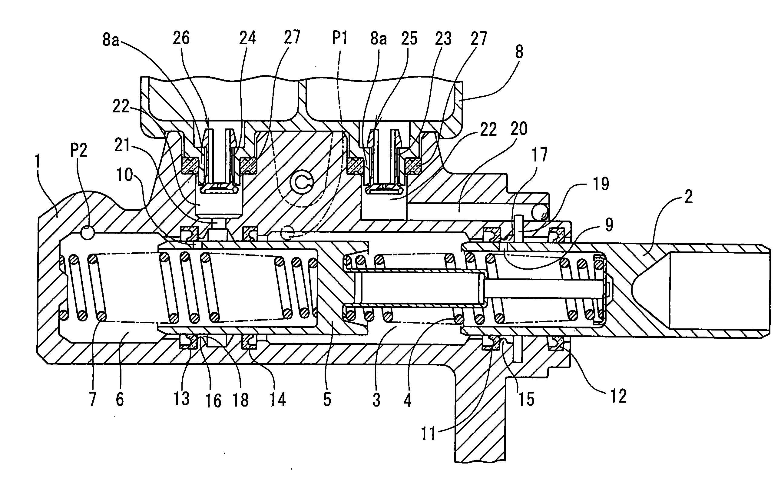
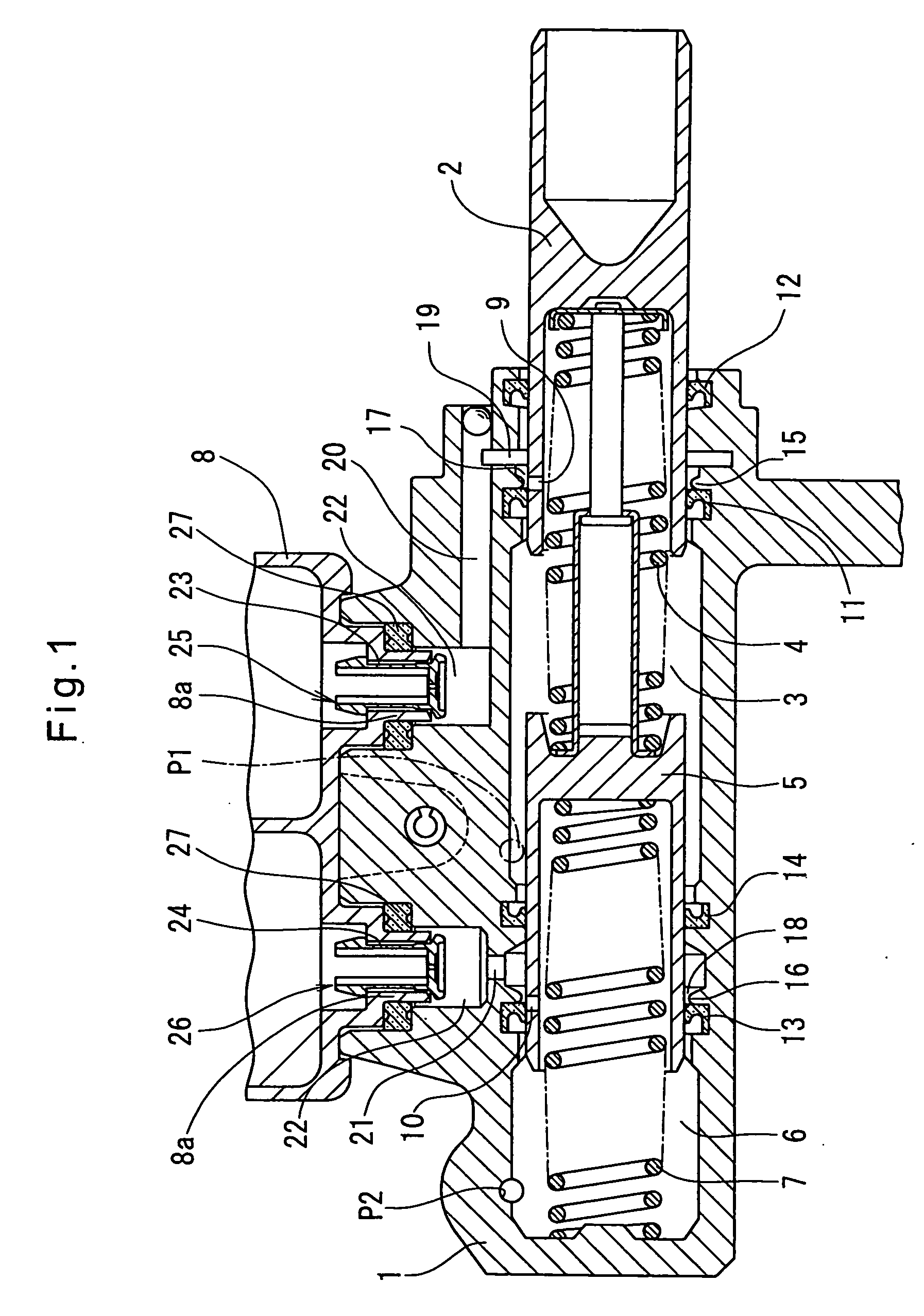
[0046] Now referring to the drawings, FIGS. 1-4 show the master cylinder of the first embodiment according to the present invention. It includes a cylinder body 1, a primary piston 2 slidably mounted in the cylinder body 1, and a secondary piston 5 slidably mounted in the cylinder body 1 forwardly (leftwardly in FIG. 1) of the primary piston 2. In the cylinder body 1, a first pressure chamber 3 is defined between the primary and secondary pistons 2 and 5, and a second pressure chamber 6 is defined between the secondary piston 5 and the end wall of the cylinder body 1. Brake hydraulic pressure is generated in each of the first and second pressure chambers 3 and 6 when hydraulic fluid filling the respective pressure chambers 3 and 6 is pressurized by the primary piston 2 and the secondary piston 5, respectively. Return springs 4 and 7 for the primary and secondary pistons 2 and 5 are mounted in the first and second pressure chambers 3 and 6, respectively. The master cylinder further i...
PUM
 Abstract
Description
Claims
Application Information