Undermount drawer slide

a drawer slide and drawer body technology, applied in drawers, furniture parts, domestic applications, etc., can solve the problems of not being easily assembled beforehand, noise, binding, durability, etc., and achieve the effect of reducing the amount of material and reducing the noise and impact for

Inactive Publication Date: 2005-10-20
GARCIE KENT CLIFTON JR
View PDF9 Cites 98 Cited by
  • Summary
  • Abstract
  • Description
  • Claims
  • Application Information

AI Technical Summary

Benefits of technology

[0015] The present invention also includes an integrated bottom for a self-closer that has a living hinge for ease of manufacturing the assembly as a one-piece construction.
[0016] Another embodiment of the present invention is an improved dampener for the roller carriages for reducing the noise and force of impact when the undermount drawer slide members contact stop elements. The improvement in the dampener of the present invention includes, at least, the inclusion of at least one elliptically shaped coil element positioned to contact a stop element of the undermount drawer slide and to absorb the shock of any impacts.
[0017] The present invention also includes a dampener for a roller carriage that has a contact face that evenly spreads the impact force when meeting a stop element.
[0018] The present invention also includes a roller carriage with a web portion that is comprised of openings that reduce the amount of material needed to fabricate the carriage and which also allow for elastic absorption of an impact force.
[0021] The present invention also includes a quick connect for an undermount drawer slide that retains its adjusted position when a drawer is removed and until it is reinstalled, thereby eliminating the need for new adjustments.

Problems solved by technology

However many of these versions suffer from a variety of problems, including noise, binding, durability, ease of assembly, to name just a few.
This also means that the prior art device has to be assembled within close proximity to the drawer slide itself and is not easily subject to being assembled beforehand and certainly not as a stand-alone completed unit.
One problem that developed with the usage of such a device, however, was the need to adjust the height or placement of the drawer.
This and the other adjustment methods suffer from a lack of precision and stability and do not normally retain their adjusted position, or at least fail to do so affirmatively, when the drawer is removed from the cabinet.

Method used


Image

  • Undermount drawer slide
  • Undermount drawer slide
  • Undermount drawer slide

Examples


Embodiment Construction

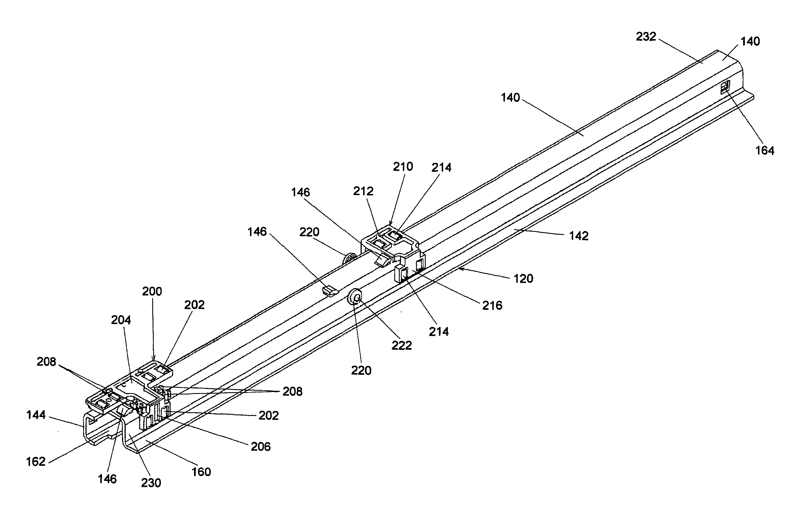
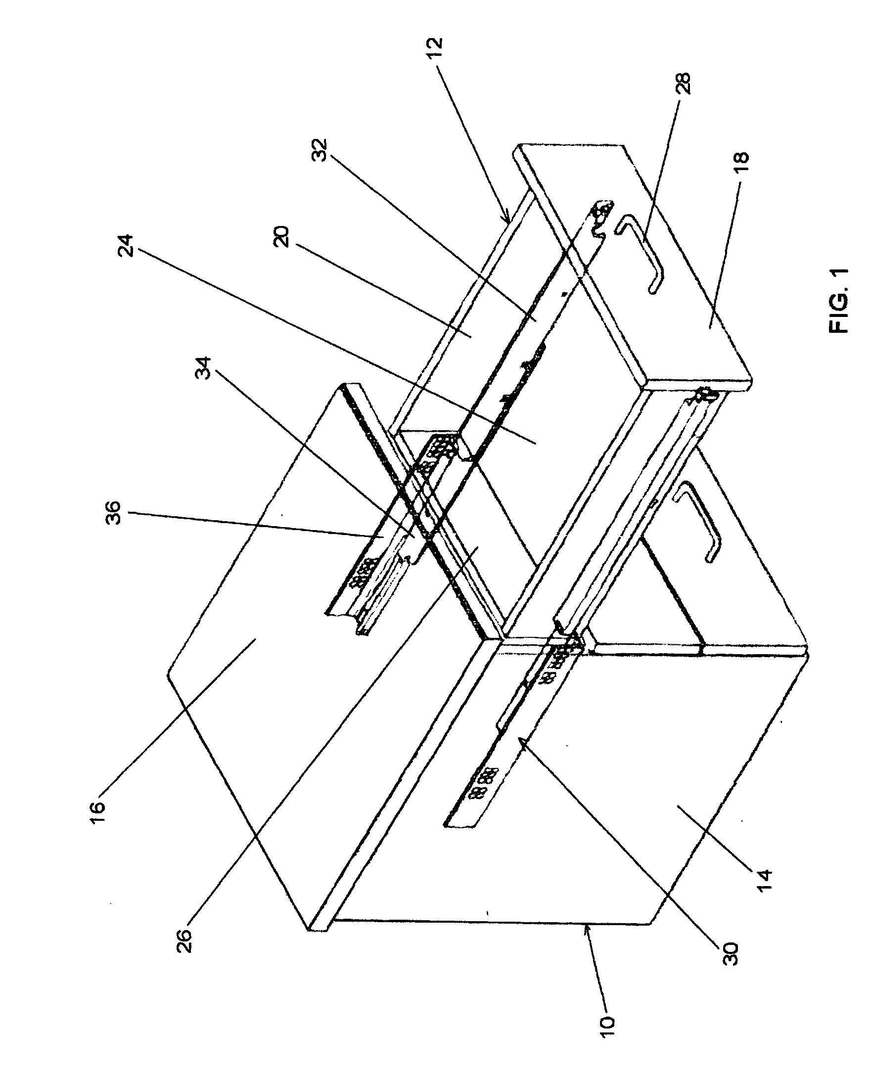
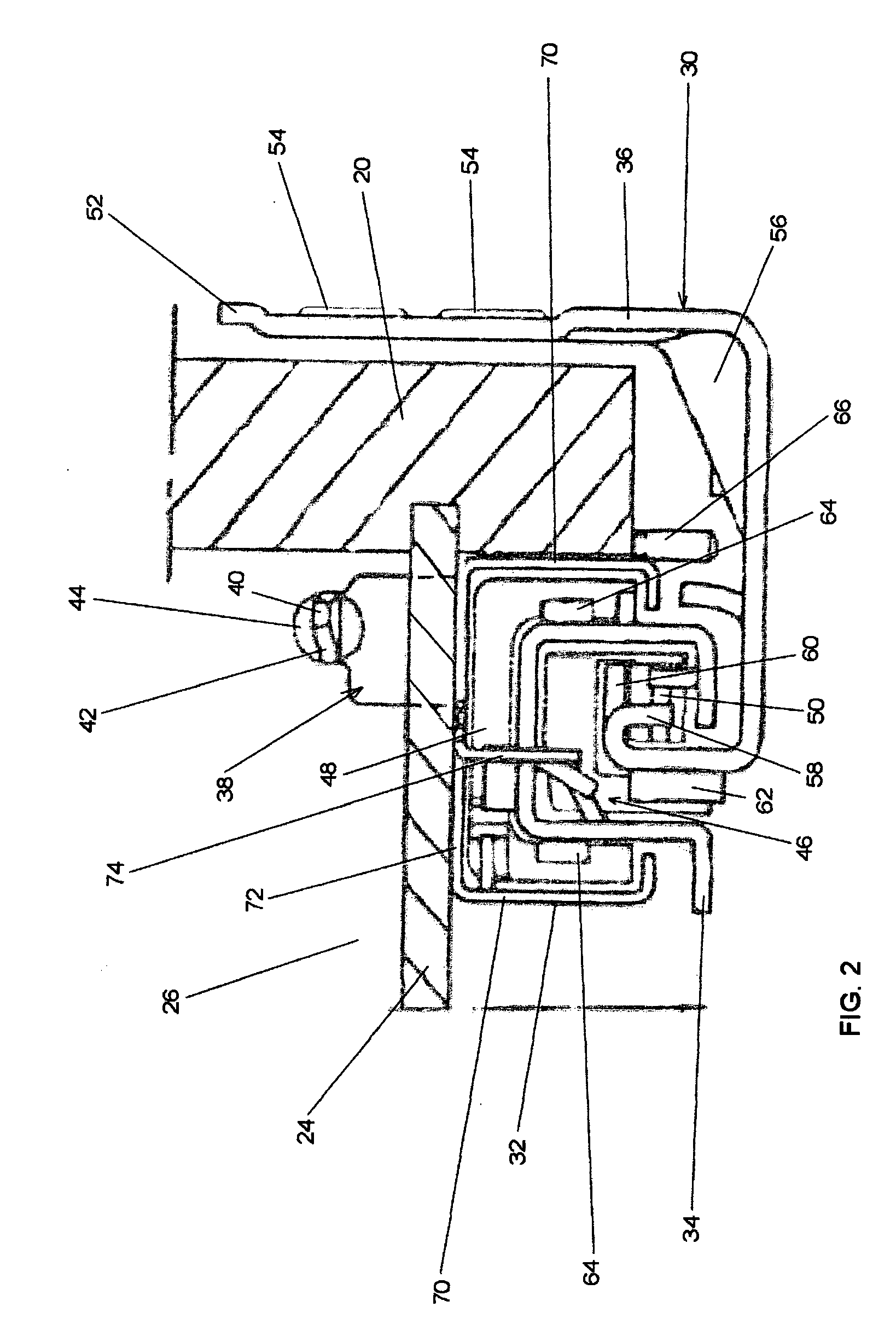
[0048] A novel undermount drawer slide of the present invention is premised upon the telescoping members typically associated with drawer slides of this type as shown in FIG. 1 and as discussed above. This arrangement is shown with more detail in FIG. 2 where the elements of the subject drawer slide and its relationship to a drawer are illustrated.

[0049] Specifically, the undermount drawer slide 30 is comprised of the drawer member 32, the intermediated member 34 and the cabinet member 36. Shown hidden behind the drawer back 26 is the drawer member tab 38 with drawer member tab point 40 with tapered point sides 42. The drawer member tab point and a substantial portion of the drawer member tab projects through the drawer back mounting hole 44 which is shown in its mounted position. The drawer back wall 26 is indicated as being coextensive from the drawer side 20 to the drawer bottom 24 and ultimately to the opposing drawer side (not shown). The typical drawer construction is indicat...


PUM


Abstract

An undermount drawer slide with a carriage for retaining rollers and for placement in between members of said drawer slide, wherein the carriage has shock absorbing stops. Also an undermount drawer slide with a one-piece self closer that is capable of being self-contained when fully assembled and which biasedly urges the undermount drawer slide assembly into a closed position when the drawer or drawer member engages the self closer. Lastly, an undermount drawer slide that has a quick connect device attached to a drawer for reversibly mounting the drawer onto an undermount drawer slide assembly, where the quick connect device includes a vertical adjustment mechanism that relies upon a toggle that is infinitely and affirmatively positionable by a threaded screw adjuster.

Description

CROSS REFERENCE TO RELATED APPLICATIONS [0001] Not applicable. STATEMENT REGARDING FEDERALLY SPONSORED RESEARCH OR DEVELOPMENT [0002] Not applicable BACKGROUND OF THE INVENTION [0003] The present invention relates to undermount drawer slides, e.g., telescoping slide rails for suspending a drawer within a cabinet. More specifically, the present invention relates to heavy duty drawer slides that are mountable underneath the bottom of a drawer in a manner where the drawer slide is largely unexposed to view when the drawer is opened. [0004] Undermount drawer slides of the type described herein, became a factor in drawer slide products during the 1980's. During this period, and extending to the present time, undermount drawer slides have been associated with European cabinet applications and the predominant undermount drawer slide manufacturers during this period of time have been European as well. These include companies like Julius Blum Gesellschaft; M.B.H. (“Blum”), Paul Hettich GmbH ...

Claims


Application Information

Patent Timeline
Patent Type & Authority Applications(United States)
IPC IPC(8): A47B88/00A47B88/04
CPCA47B88/047A47B2210/0097A47B2210/0056A47B2210/0032A47B88/467
Inventor GARCIE, KENT CLIFTON JR.
Owner GARCIE KENT CLIFTON JR
Why Eureka
Try Eureka