Lighting installation with regulation of light emission devices

a technology of light emission device and light emission, which is applied in the field of light emission device regulation of lighting installation, can solve the problems of limiting the flexibility of use, affecting the use of the device, and the necessity of providing two connection lines (to the electrical power supply and to the potentiometer), so as to facilitate the regulation of light emission and reduce the luminous flux. , the effect of easy regulation of light emission

Inactive Publication Date: 2005-10-20
POWER ONE ITAL +1
View PDF9 Cites 19 Cited by
  • Summary
  • Abstract
  • Description
  • Claims
  • Application Information

AI Technical Summary

Benefits of technology

[0013] According to one specific aspect, the object of a particular embodiment of the invention is to provide an installation which enables the user to easily regulate the light emission of one or more lighting fittings, particularly in a closed environment.
[0014] According to a different aspect, the object of a particular embodiment is to provide an installation which permits easy regulation of the luminous flux in a street lighting installation, for urban centers for example, to reduce the luminous flux during the night.

Problems solved by technology

Then this operation has to be carried out in an apartment or in a workplace, it will cause considerable problems and inconveniences, in addition to the costs due to this operation.
Even when the use of a dimmable lamp is specified in a newly produced installation, the necessity of providing two connection lines (to the electrical power supply and to the potentiometer) complicates the installation.
This evidently limits the flexibility of use.
Moreover, while it is easy to provide a plurality of on-off switches 7 at different points of a single environment or apartment, it is difficult to be able to regulate the light emission from a plurality of dispersed points.
In the lighting of public places, urban centers, highways and the like, there arises a similar problem of reducing the light flux of lamps in the middle of the night, in order to save energy.
This system has considerable drawbacks.
This is because the power supply line of the lighting units is frequently very extended and therefore considerable losses of load occur in the line, especially when the voltage is reduced.
The discharge lamps used for this type of application cannot remain illuminated if the supply voltage falls below a certain minimum value.
In many situations, therefore, the lighting units farthest from the flux regulator, whose terminals receive a voltage which is lower than that at the output of the flux regulator, due to losses in the supply line, cannot remain illuminated.

Method used


Image

  • Lighting installation with regulation of light emission devices
  • Lighting installation with regulation of light emission devices
  • Lighting installation with regulation of light emission devices

Examples


Embodiment Construction

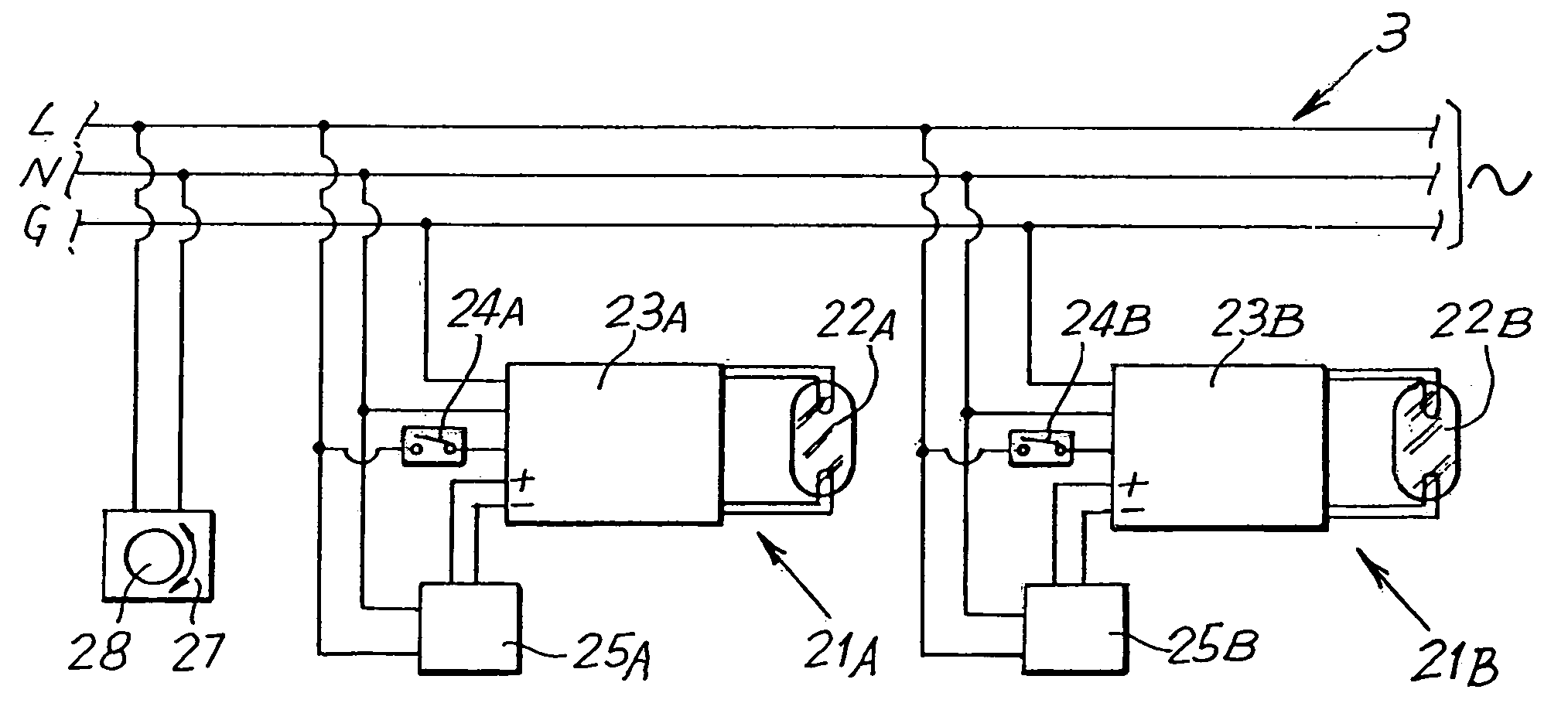
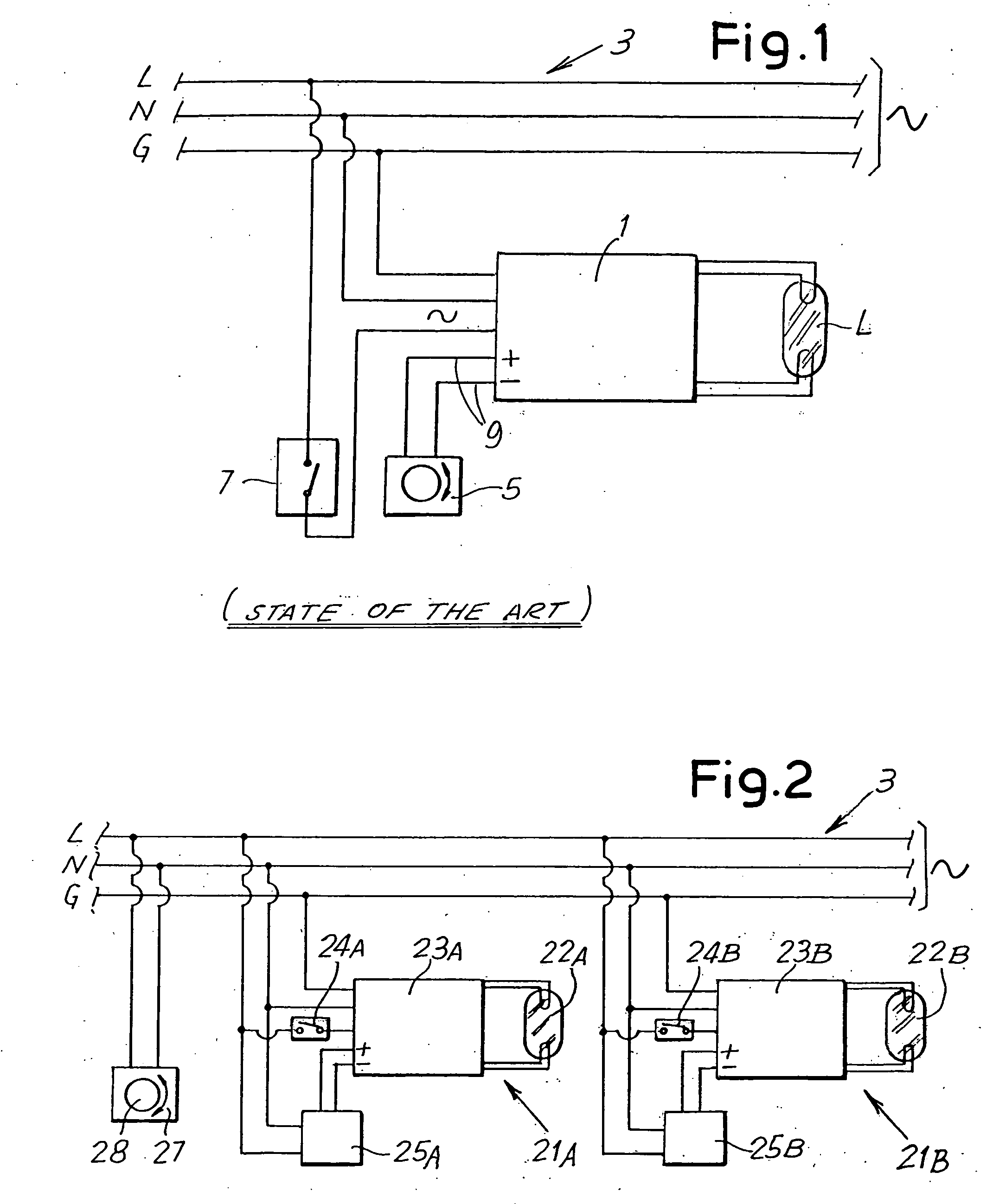
[0031]FIG. 2 shows a portion of a lighting installation, for example in an apartment or the like, produced according to a first embodiment of the invention. The number 3 indicates the electrical power supply line, the live, neutral and ground lines of which are indicated by L, N and G. The numbers 21A and 21B indicate the whole of two lighting devices, each comprising a corresponding lamp 22A, 22B. Each lamp is supplied from a dimmable ballast 23A, 23B of a known type which is not described in detail. Each dimmable ballast has terminals for connection to the live line L and to the neutral N for the electrical power supply to the lamp, and a terminal for connection to the ground G. An on-off switch 24A, 24B is provided for each lighting device 21A, 21B in the connection to the live line L of the electrical power supply line 3. Additionally, each ballast has, in a known way, regulation connectors or terminals, for a low-voltage signal for regulating the intensity of light emission of ...


PUM


Abstract

The lighting installation comprises an electrical power supply line (3) and at least one lighting device (21A; 21B; 21C) with controllable light emission, connected to said electrical power supply line (3). Each lighting device is associated with a control unit (25A, 25B, 25C) comprising a device (30) for receiving data transmitted along the electrical power supply line (3) and devices (41; 60) for generating a light emission regulation signal. The electrical power supply line is connected to a controller (27) with a means (83) of transmitting data toward the control unit (25A, 25B, 25C). Additionally, the controller is programmed to send at least one data element to the control unit for regulating the emission of the corresponding lighting device.

Description

BACKGROUND OF THE INVENTION [0001] The present invention relates to a lighting system, for example a lighting system for domestic or work premises, but also for public places, hotel or industrial buildings, urban centers, streets, and generally for environments in which it is useful or necessary to provide lamps or lighting fittings which have a light intensity regulation function, or which in other words are “dimmable”. [0002] Lamps known as “dimmable”, in other words those provided with regulators of their light emission, are used increasingly often for lighting many environments, particularly domestic and work environments. [0003] Lamps fitted with these devices can be regulated in such a way as to vary the light intensity according to the requirements of the user and / or the ambient light, for example the light from a window. Typically, dimmable ballasts, in other words ballasts containing brightness regulation circuits, are provided for regulating the light emission of HID lamps...

Claims


Application Information

Patent Timeline
Patent Type & Authority Applications(United States)
IPC IPC(8): G05F1/00H05B37/02
CPCH05B37/0263H05B47/185
Inventor BECATTINI, ANDREA
Owner POWER ONE ITAL
Why Eureka
Try Eureka