Constant voltage circuit

a constant voltage and circuit technology, applied in the direction of electric variable regulation, process and machine control, instruments, etc., can solve the problems of relatively slow response speed of responding to an input voltage vin or a load current change abruptly, and achieve the effect of increasing the response speed

Inactive Publication Date: 2005-10-20
RICOH ELECTRONIC DEVICES CO LTD
View PDF11 Cites 52 Cited by
  • Summary
  • Abstract
  • Description
  • Claims
  • Application Information

AI Technical Summary

Benefits of technology

[0012] The present invention has been conceived in response to one or more of the problems of the related art, and it object is to provide a constant voltage circuit that is capable of increasing the response speed for responding to an abrupt change in an input voltage or a load current.
[0020] According to another preferred embodiment of the present invention, the response speed of the second error amplifier for responding to a change in the output voltage is arranged to be faster than the response speed of the first error amplifier for responding to the change in the output voltage.

Problems solved by technology

However, in such an arrangement, a relatively long period of time is needed to charge the condenser C101 of the frequency compensation circuit and the input capacitance of the output voltage control transistor M101, and consequently, the response speed for responding to an abrupt change in an input voltage Vin or a load current may be relatively slow.

Method used


Image

  • Constant voltage circuit
  • Constant voltage circuit
  • Constant voltage circuit

Examples


first embodiment

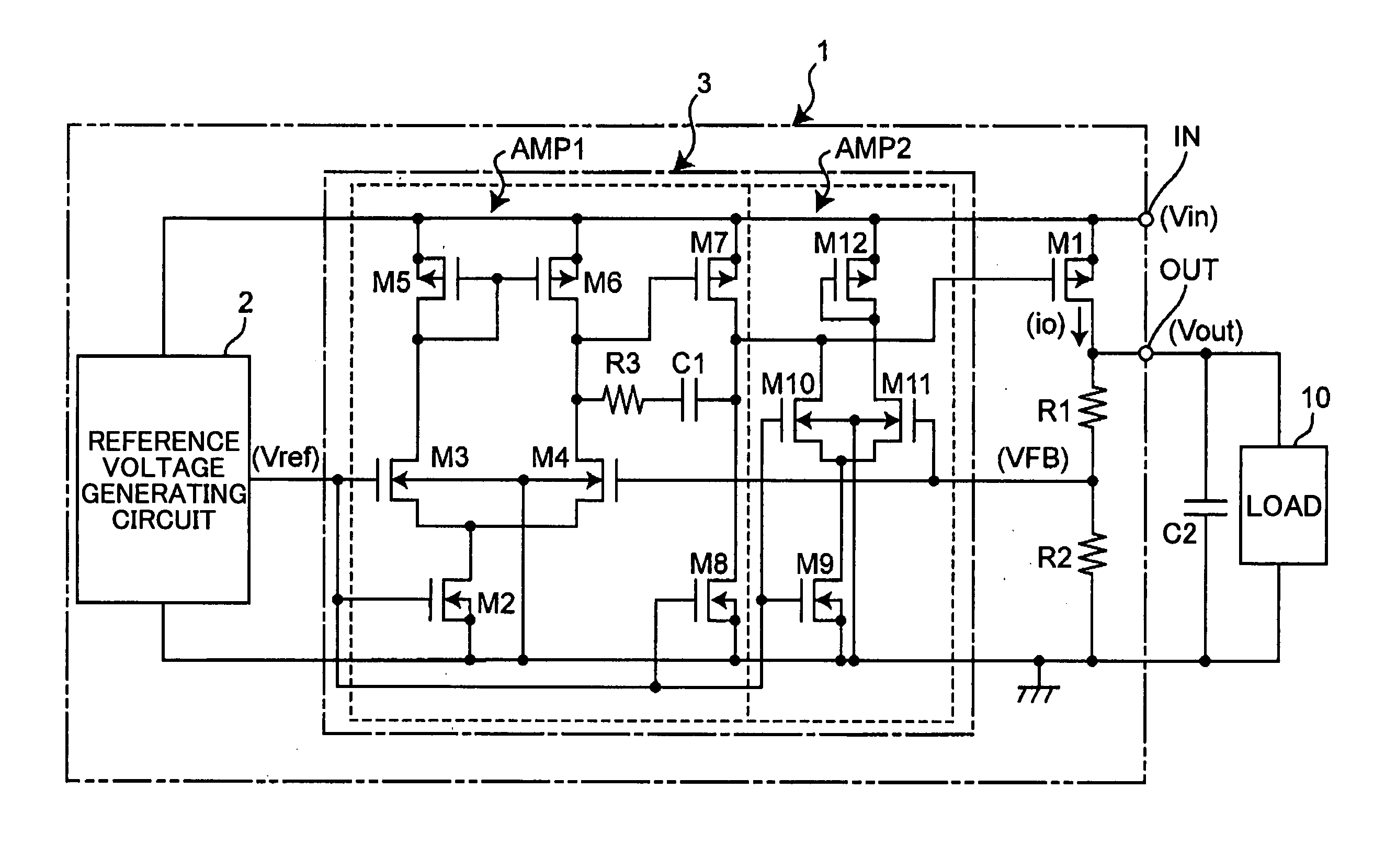
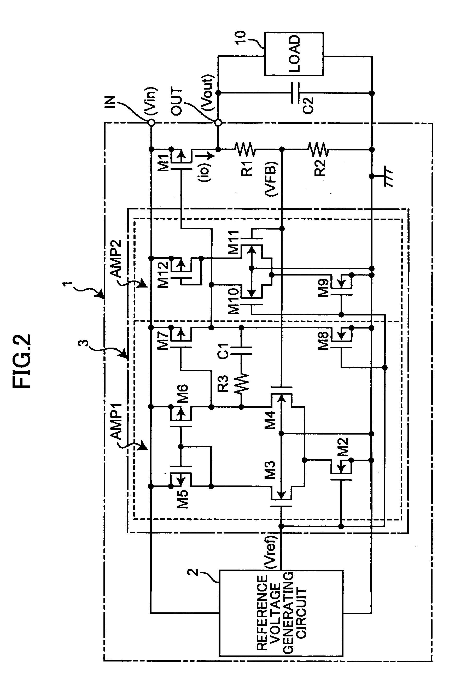
[0046]FIG. 2 is a circuit diagram showing an exemplary configuration of a constant voltage circuit according to a first embodiment of the present invention.

[0047] The constant voltage circuit 1 of FIG. 2 generates a predetermined constant voltage from an input voltage Vin and outputs the generated constant voltage via an output terminal OUT. It is noted that a load 10 and a condenser C2 are connected in parallel between the output terminal OUT and the ground voltage.

[0048] The constant voltage circuit 1 includes a reference voltage generating circuit 2 that generates and outputs a predetermined reference voltage Vref, output voltage detection resistors R1 and R2 that divide an output voltage Vout to generate and output a divided voltage VFB, an output voltage control transistor M1 corresponding to a PMOS transistor that controls a current io that is output to the output terminal OUT according to a signal input to its gate, and an error amplifying circuit unit 3 that controls the o...

second embodiment

[0063]FIG. 4 is a circuit diagram showing a configuration of a constant voltage circuit according to a second embodiment of the present invention.

[0064] The constant voltage circuit 201 of FIG. 4 generates a predetermined constant voltage from an input voltage Vin and outputs the generated voltage as an output voltage Vout via an output terminal OUT. It is noted that a load 210 and a condenser 202 are connected in parallel between the output terminal OUT and the ground voltage.

[0065] The constant voltage circuit 201 includes a first reference voltage generating circuit 202 that generates and outputs a predetermined reference voltage Vr, a second reference voltage generating circuit 203 that generates and outputs a predetermined reference voltage Vb1, a third reference voltage generating circuit 204 that generates and outputs a predetermined bias voltage Vb2, output voltage detection resistors R201 and R202 that generate and output a divided voltage VFBb of the output voltage Vout,...


PUM


Abstract

A constant voltage circuit that is capable of realizing high speed response with respect to an abrupt change in an input voltage or a load current is disclosed. The constant voltage circuit includes a first error amplifier with a high direct current gain and a second error amplifier with high speed responsiveness with respect to a change in an output voltage. The constant voltage circuit uses the first and second error amplifiers to conduct operation control of an output voltage control transistor in response to a change in the output voltage.

Description

BACKGROUND OF THE INVENTION [0001] 1. Field of the Invention [0002] The present invention relates generally to a constant voltage circuit that uses an error amplifier, and particularly to a technique for increasing the response speed for responding to an abrupt change in an input voltage or a load current. [0003] The present invention also relates to a constant voltage circuit that uses an error amplifier including a frequency compensation circuit that conducts phase compensation. [0004] 2. Description of the Related Art [0005] Conventionally, an error amplifier used in a constant voltage circuit includes a frequency compensation circuit that conducts phase compensation in order to prevent unstable operation such as oscillation. [0006]FIG. 1 is a circuit diagram showing an exemplary configuration of a constant voltage circuit according to the prior art. [0007] In the constant voltage circuit 100 of FIG. 1, an error amplifier AMPa includes NMOS transistors M103 and M104 that realize ...

Claims


Application Information

Patent Timeline
Patent Type & Authority Applications(United States)
IPC IPC(8): G05F1/40G05F1/575
CPCG05F1/575
Inventor NAGATA, TOSHIHISAYOSHII, KOHJIMINAKUCHI, YUSUKE
Owner RICOH ELECTRONIC DEVICES CO LTD
Why Eureka
Try Eureka