Drive control apparatus, electronic apparatus, method of controlling drive of electronic apparatus, drive control program, and recording medium
a technology of electronic equipment and control apparatus, which is applied in the direction of generating/distributing signals, piezoelectric/electrostrictive device details, and horology, etc., can solve the problems of imposing limitations on the use of power sources, and prolonging the entire intermittent driving time. , to achieve the effect of reducing the drive time, the device, and reducing the size of the power sour
- Summary
- Abstract
- Description
- Claims
- Application Information
AI Technical Summary
Benefits of technology
Problems solved by technology
Method used
Image

Examples
first embodiment
1. First Embodiment
[0051] The first embodiment of the present invention will now be described with reference to the diagrams.
1-1. Entire Configuration
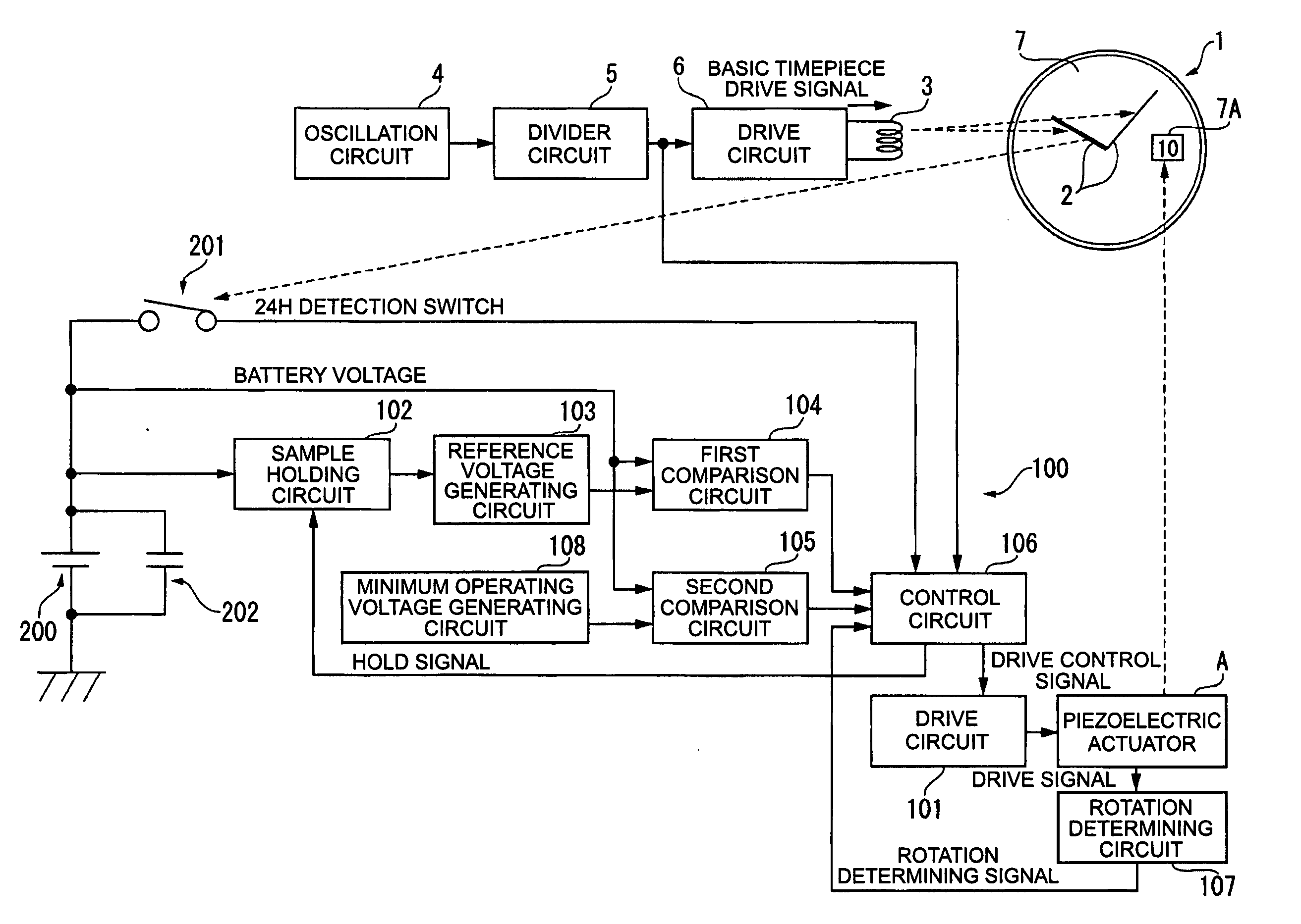
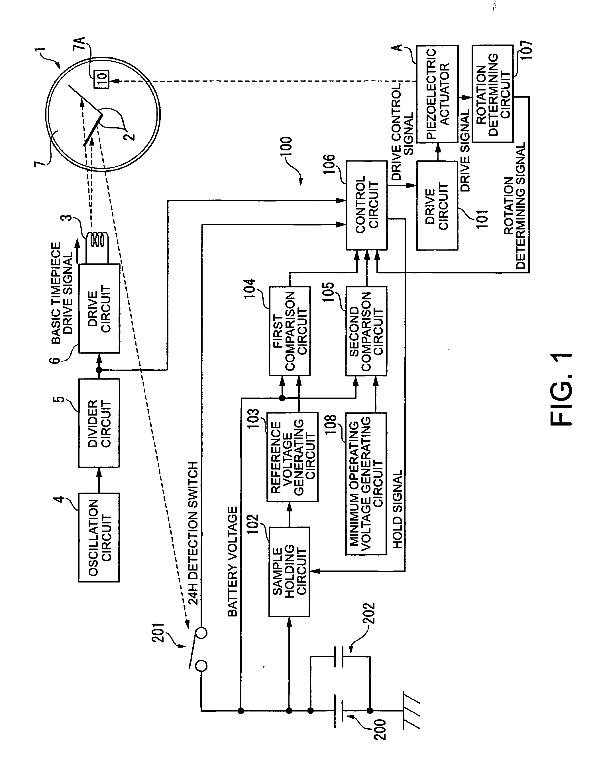
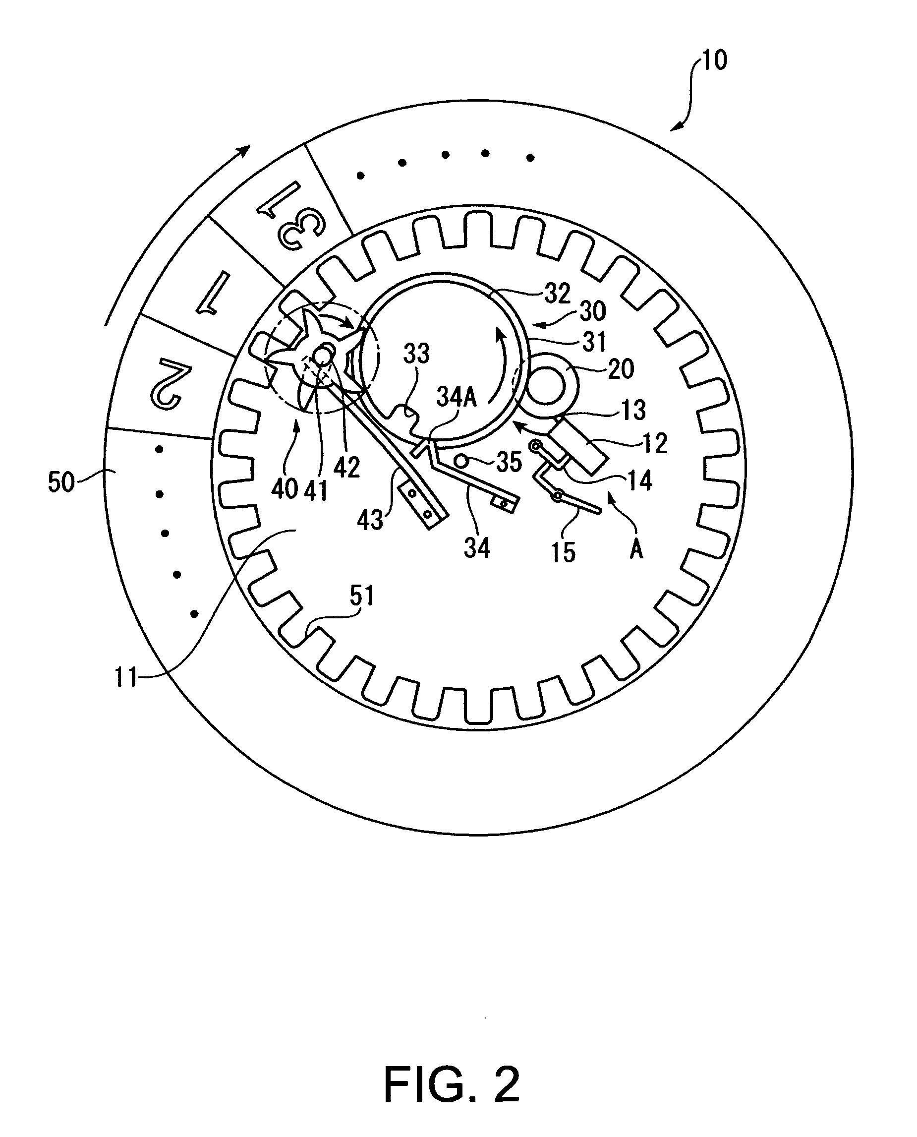
[0052]FIG. 1 is a block diagram showing the configuration of the drive apparatus for an electronic timepiece 1 and a date display mechanism 10 thereof in the present embodiment. FIG. 2 is a plan view showing the detailed configuration of the date display mechanism 10.
[0053] As shown in FIG. 1, the electronic timepiece 1 is a wristwatch that has pointers 2 for displaying the time, and a stepping motor 3 for driving the pointers 2. The driving of the stepping motor 3 is controlled by an oscillation circuit 4, a divider circuit 5, and a drive circuit 6. The oscillation circuit 4 has a standard oscillation source composed of a crystal oscillator, and outputs a standard pulse. The divider circuit 5 inputs the standard pulse outputted from the oscillation circuit 4, and produces a standard signal (a signal of 1 Hz, for example) on the bas...
second embodiment
2. Second Embodiment
[0093] Next, the second embodiment of the present invention will be described.
[0094] In the second embodiment, the electronic timepiece 1 and the drive control apparatus 100 have the same configuration as in the above-described first embodiment, but the drive control method is different.
[0095] Specifically, in steps S7 and S8 of the first embodiment, driving is controlled so that the driving of the piezoelectric actuator A is stopped and the battery voltage V0 is once again held by the sample holding circuit 102 when the elapsed time T exceeds the set time T0 after the basic timepiece drive signal from the divider circuit 5 is received.
[0096] In the second embodiment, the steps S7 and S8 of the first embodiment are omitted. Specifically, driving is executed without holding the battery voltage V0 one more time while the piezoelectric actuator A is driven.
2-1. Drive Control Method of the Piezoelectric Actuator A
[0097] As shown in the timing chart in FIG. 5, af...
third embodiment
3. Third Embodiment
[0100] Next, the third embodiment of the present invention will be described with reference to FIG. 6.
[0101] The configuration and operation (control method) of the electronic timepiece 1 as the electronic device according to the present embodiment are substantially the same as in the first embodiment, and detailed descriptions thereof are omitted. The electronic timepiece 1 of the present embodiment has a characteristic relationship between the storage battery 200 as a power source, and the time display section and the date display mechanism 10. This characteristic is described in detail below.
[0102]FIG. 6 is a block diagram showing the electronic timepiece configuration of the electronic timepiece 1 as the electronic device according to the present embodiment.
[0103] In FIG. 6, the storage battery (high-capacity capacitor) 200, which is the power source of the electronic timepiece 1, is charged with electric power from a power generator 203, and the charged el...
PUM
 Abstract
Description
Claims
Application Information
 - R&D
- Intellectual Property
- Life Sciences
- Materials
- Tech Scout
- Unparalleled Data Quality
- Higher Quality Content
- 60% Fewer Hallucinations
Browse by: Latest US Patents, China's latest patents, Technical Efficacy Thesaurus, Application Domain, Technology Topic, Popular Technical Reports.
© 2025 PatSnap. All rights reserved.Legal|Privacy policy|Modern Slavery Act Transparency Statement|Sitemap|About US| Contact US: help@patsnap.com