
Imaging apparatus, imaging system, imaging apparatus control method and control program, and recording medium in which the same program has been recorded

a technology of imaging apparatus and control method, which is applied in the direction of electric signalling details, instruments, television systems, etc., can solve the problems of theft and misuse of transportable cameras, affecting the monitoring of designated places, and affecting the use of designated places

Inactive Publication Date: 2005-10-20
ORMON CORP
View PDF0 Cites 26 Cited by
  • Summary
  • Abstract
  • Description
  • Claims
  • Application Information

AI Technical Summary

Benefits of technology

The present invention provides an image pickup equipment, system, and method that can prevent improper use of the camera, such as stolen or unauthorized use. The image pickup equipment includes a self-location detecting section that can determine the location of the equipment, and a location determining section that can determine if the location is inside or outside of a predetermined area. If the location is outside of the predetermined area, the image pickup operation is restricted to prevent improper use. The image pickup equipment can be made up of an optical system and a signal processing system that converts input light to obtain image data. The system can also include a server computer that receives image information from the image pickup equipment and utilize it for various purposes.

Problems solved by technology

If a camera being set up is carried away by an ill-motivated person or a child, not only the monitoring of the designated place becomes impossible but also the stolen camera may be abused for improper use such as sneak shot and other privacy infringing purposes.
In particular, transportable cameras (e.g. cameras supporting wireless communications and power line communications) are significantly prone to the aforesaid theft and misuse.
This problem of the theft and misuse of the camera has obstructed the proliferation of the image monitoring system in the society, and hence has been a high-priority issue to be solved.

Method used


Image

  • Imaging apparatus, imaging system, imaging apparatus control method and control program, and recording medium in which the same program has been recorded
  • Imaging apparatus, imaging system, imaging apparatus control method and control program, and recording medium in which the same program has been recorded
  • Imaging apparatus, imaging system, imaging apparatus control method and control program, and recording medium in which the same program has been recorded

Examples


Embodiment Construction

[0036] One embodiment of the present invention is described below with reference to the attached drawings.

[0037] [System Configuration]

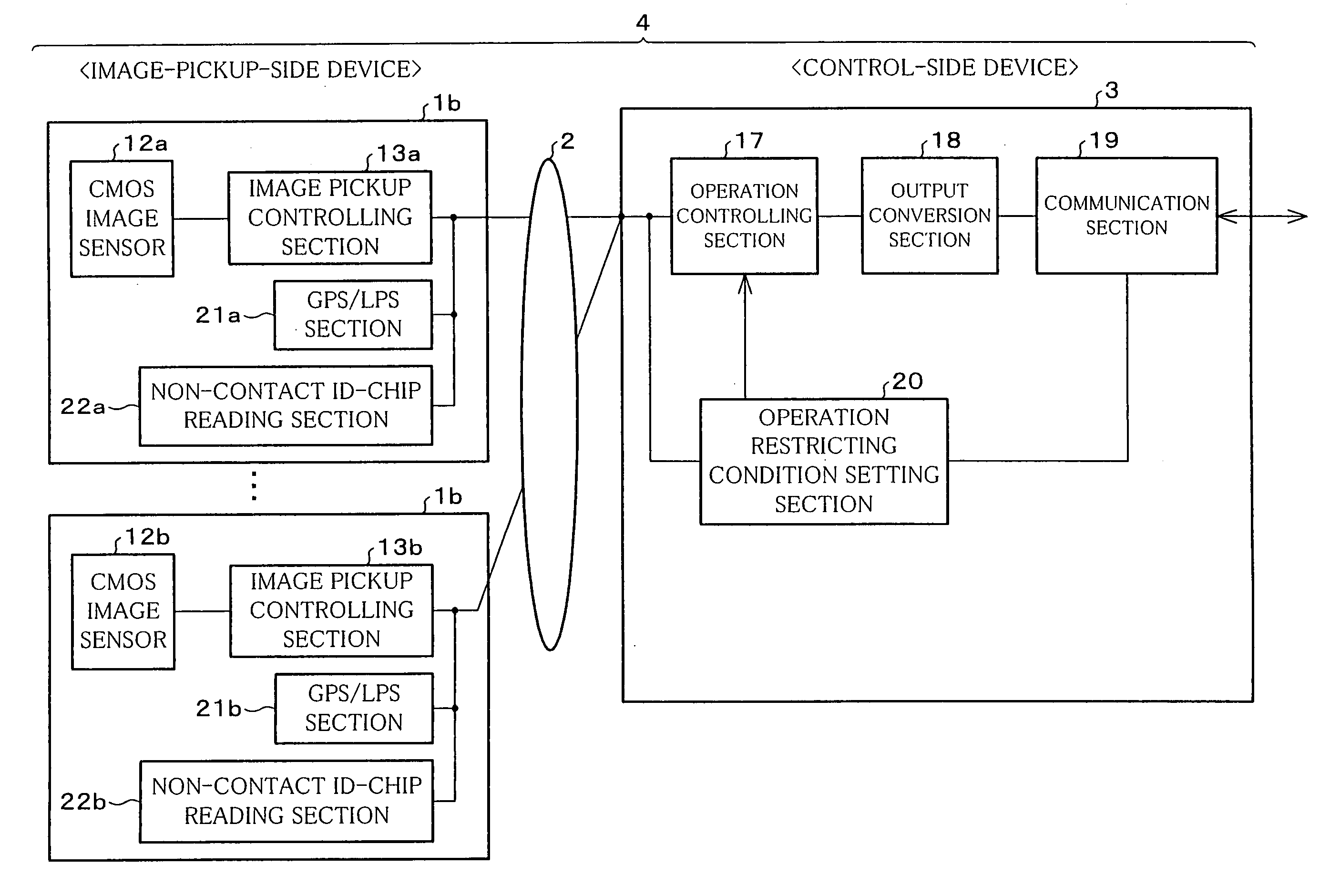
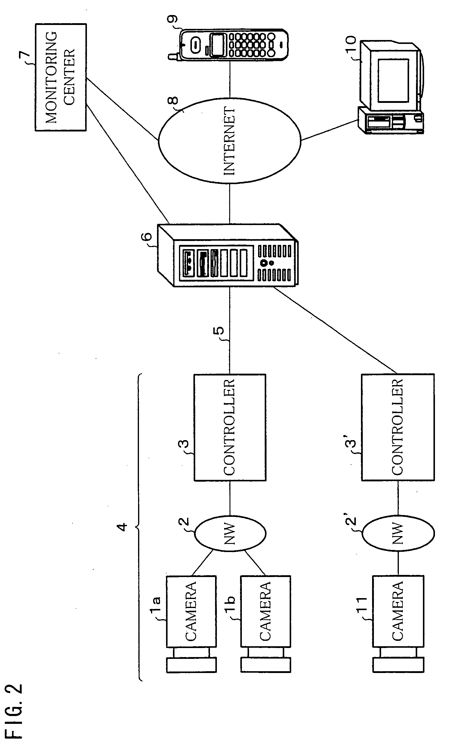
[0038] An image monitoring system (image pickup system) of the present embodiment is structured as illustrated in FIG. 2. That is, in this image monitoring system, a network camera (image pickup equipment) 4 including a plurality of cameras 1a, 1b, . . . (hereinafter, collectively termed cameras 1), an image-pickup communications network (NW) 2, and controllers 3 is connected to a center (server computer) 6 through the intermediary of a communications network 5. As shown in the figure, one camera 11, an image-pickup communications network (NW) 2′, and a controller 3′ may be connected to the center 6, in place of the network camera 4.

[0039] The center 6 is connected to a monitoring center 7, via a circuit switched connection or the Internet 8. The center 6 is further connected to a mobile phone 9 and a personal computer 10 via the Internet 8. Note t...


PUM


Abstract

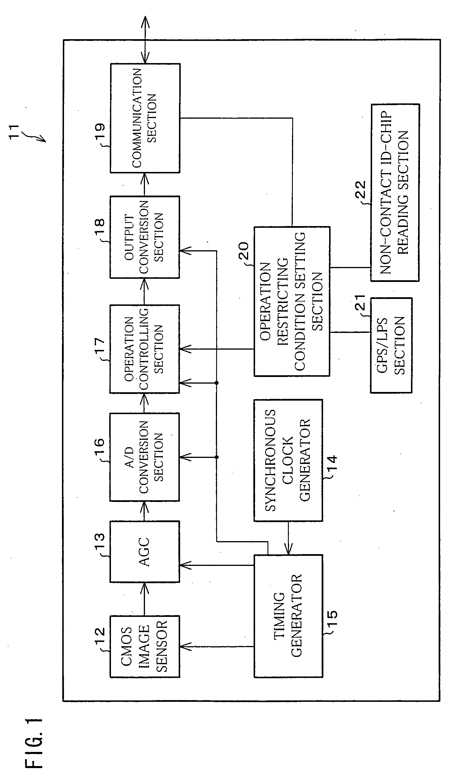
A camera (11) includes: a CMOS image sensor (12) which converts input light so as to obtain image data; a GPS / LPS section (21) or a non-contact ID-chip reading section (22), which detects the location of the camera itself; an operation restricting condition setting section (20) which determines whether or not the detected location is inside of a predetermined area; and an operation controlling section (17). If it is determined that the location of the camera itself is outside of the predetermined area, the operation controlling section (17) restricts the image pickup operation in the CMOS sensor (12).

Description

TECHNICAL FIELD [0001] The present invention relates to an image pickup equipment for monitoring an area, an image pickup system, a method and program for controlling the image pickup equipment, and a storage medium storing the program. BACKGROUND ART [0002] Image monitoring systems (image pickup systems) provide a monitoring / controlling service and other types of services, using data of images taken by cameras covering specific areas such as an office building, a store, and a house. Such image monitoring systems have rapidly become popular. An image monitoring system is made up of cameras set up on a plurality of places and a monitoring server for collectively managing these cameras. Sets of image information of images taken by the cameras are transmitted to the monitoring server via a communications network, and the monitoring server checks if an abnormal event occurs. [0003] The scope of such a image monitoring system is remarkably wide. For instance, there is a system that adopt...

Claims


Application Information

Patent Timeline
Patent Type & Authority Applications(United States)
IPC IPC(8): H04N5/225H04N5/232H04N7/18
CPCH04N7/18
Inventor KANAYAMA, KENJISUZUKI, TOSHIHIRO
Owner ORMON CORP
Learn More