Augmented reality traffic control center

a traffic control center and augmented reality technology, applied in the field of air traffic control systems, can solve the problems of air traffic adding a third dimension of altitude, severely affecting the operation of conventional traffic control centers, and affecting the primary flight control of aircraft carriers,

Inactive Publication Date: 2005-10-20
LOCKHEED MARTIN CORP +1
View PDF16 Cites 117 Cited by
  • Summary
  • Abstract
  • Description
  • Claims
  • Application Information

AI Technical Summary

Benefits of technology

[0008] An exemplary embodiment of the present invention provides a traffic controller, such as an air traffic controller, with more data than a conventional radar-based air traffic control system, especially in conditions with low visibility such as low cloud cover or nightfall. The system can provide non-visual data, such as, e.g., but not limited to, infrared and ultraviolet data, about traffic control objects, and can display that information in real-time on displays that simulate conventional glass-window control tower views. In addition, the system can track the movements of the controller and receive the movements as selection inputs to the system.

Problems solved by technology

Operations in conventional traffic control centers, such as, e.g., primary flight control on an aircraft carrier, airport control towers, and rail yard control towers, are severely impacted by reduced visibility conditions due to fog, rain and darkness, for example.
Unfortunately, unlike automobile traffic control systems which deal with two dimensional road systems, air traffic adds a third dimension of altitude.
Unfortunately, conventional display systems are two dimensional and the controller must mentally extrapolate, e.g., a 2D radar image into a three dimensional (3D) representation and also project the flight path in time in order to prevent collisions between the aircraft.
These radar-based systems are inefficient, however, at collecting and conveying three or more dimensional data to the controller.
If an unknown or unanticipated aircraft enters the control space, the control center may not be able to communicate with it.

Method used


Image

  • Augmented reality traffic control center
  • Augmented reality traffic control center
  • Augmented reality traffic control center

Examples


Embodiment Construction

[0022] A preferred embodiment of the invention is discussed in detail below. While specific exemplary embodiments are discussed, it should be understood that this is done for illustration purposes only. A person skilled in the relevant art will recognize that other components and configurations can be used without parting from the spirit and scope of the invention.

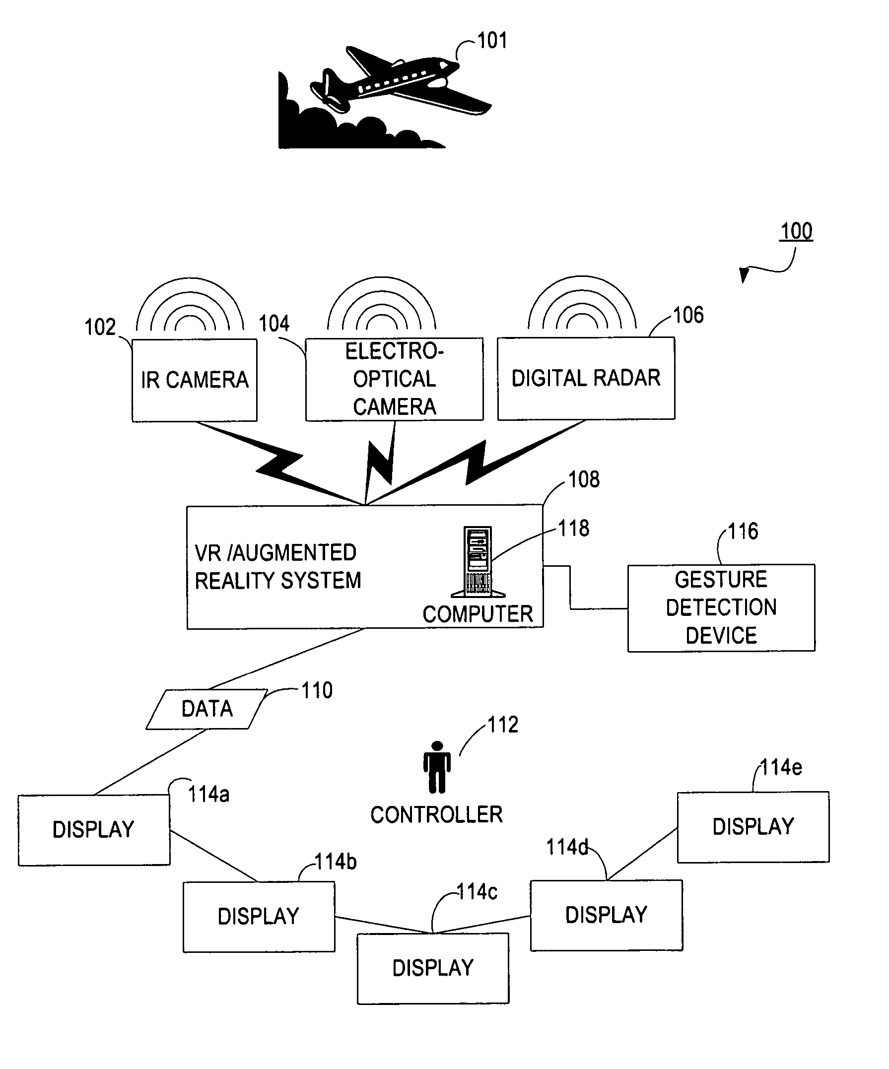
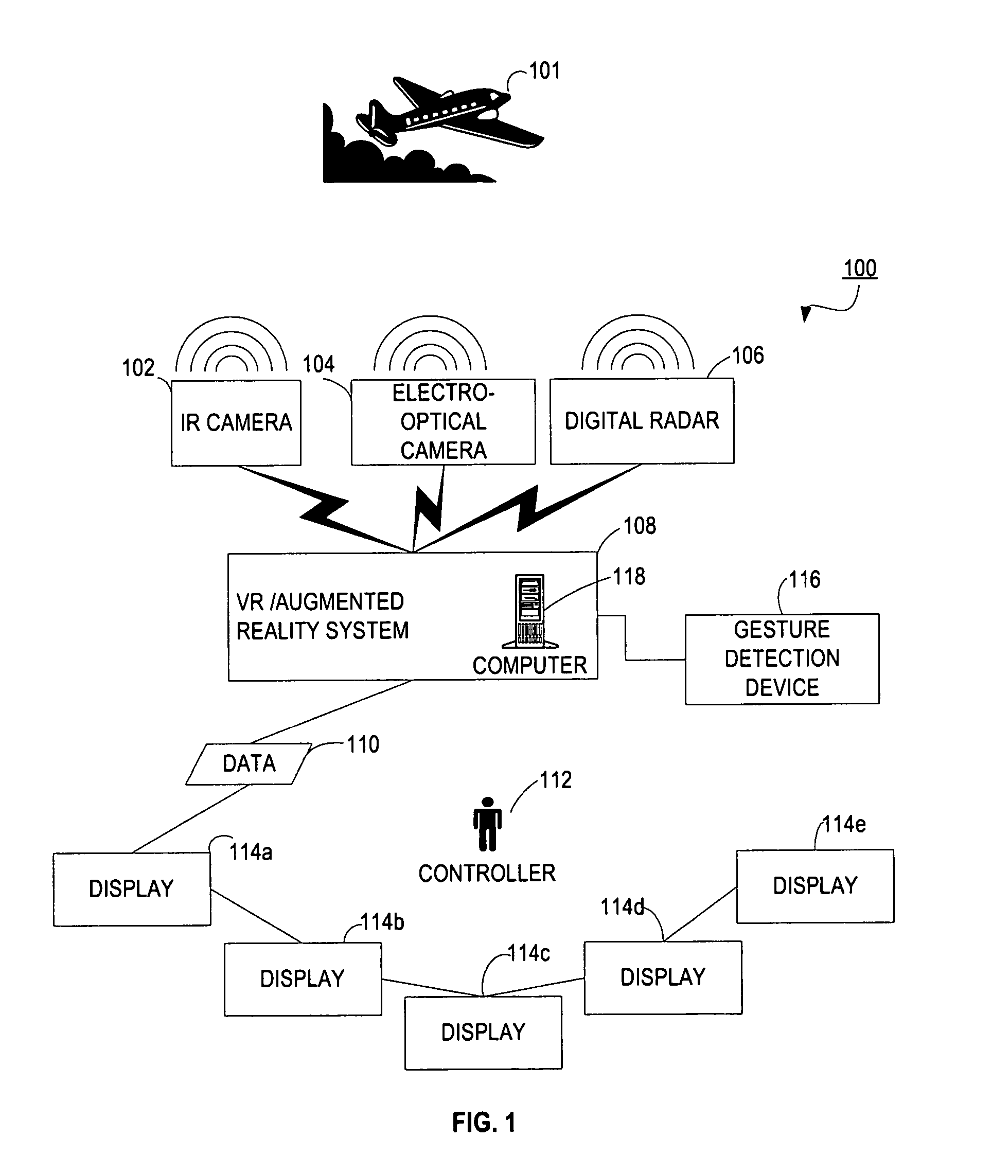
[0023] As seen in FIG. 1, in an exemplary embodiment, an air traffic control system 100 can use different types of sensors and detection equipment to overcome visibility issues. For example, the system 100 can use infrared (IR) cameras 102, electro-optical (EO) cameras 104, and digital radar 106, alone or in combination, to collect visual and non-visual data about an air traffic control object, such as, e.g., but not limited to, airplane 101. Additional sensors can include, e.g., but are not limited to, a radio-frequency image sensor, RADAR, LIDAR, a millimeter wave imaging sensor, an acoustic sensor, a digital infrared c...


PUM


Abstract

In an exemplary embodiment, an augmented reality system for traffic control combines data from a plurality of sensors to display, in real time, information about traffic control objects, such as airplanes. The sensors collect data, such as infrared, ultraviolet, and acoustic data. The collected data is weather-independent due to the combination of different sensors. The traffic control objects and their associated data are then displayed visually to the controller regardless of external viewing conditions. The system also responds to the controller's physical gestures or voice commands to select a particular traffic control object for close-up observation or to open a communication channel with the particular traffic control object.

Description

BACKGROUND OF THE INVENTION [0001] 1. Field of the Invention [0002] The present invention relates generally to traffic control systems, and more particularly to air traffic control systems. [0003] 2. Related Art [0004] Operations in conventional traffic control centers, such as, e.g., primary flight control on an aircraft carrier, airport control towers, and rail yard control towers, are severely impacted by reduced visibility conditions due to fog, rain and darkness, for example. Traffic control systems have been designed to provide informational support to traffic controllers. [0005] Conventional traffic control systems make use of various information from detectors and the objects being tracked to show the controller where the objects are in two dimensional (2D) space. For example, an air traffic control center in a commercial airport, or on a naval aircraft carrier at sea, typically uses a combination of radar centered at the control center and aircraft information from the airp...

Claims


Application Information

Patent Timeline
Patent Type & Authority Applications(United States)
IPC IPC(8): G01S13/91G08G5/00
CPCG08G5/0082G08G5/0026
Inventor MITCHELL, STEVEN W.
Owner LOCKHEED MARTIN CORP
Why Eureka
Try Eureka